Resin distributing device

A dispensing device and resin technology, applied in the direction of suspension devices, packaging, and devices for coating liquid on the surface, etc., can solve the problems of large maintenance, complex structure, etc., to ensure the reliability of the device, realize the attenuation function, The effect of expanding the scope of application

Active Publication Date: 2009-06-17
PROTEC CO LTD
View PDF5 Cites 2 Cited by
  • Summary
  • Abstract
  • Description
  • Claims
  • Application Information

AI Technical Summary

Problems solved by technology

[0014] In addition, although the setting conditions of the resin dispensing device to be used will vary depending on the viscosity, thixotropy (image retention), flow characteristics, temperature safety, and adhesive properties of the adhesive (resin) to be applied, but the best It is important to dispense pressure, dispense time (dispense speed) to have the greatest impact
[0015] However, in the distribution of this type of resin in the past, there are the following disadvantages: the interchangeability of equipment cannot be provided according to the characteristics of the resin (adhesive), the realization of the equipment is very complicated, and the decomposition of the cleaning parts according to the applied resin, Assembly is relatively difficult, the stroke adjustment of the dot rod is complicated, and the realization of the front end buffer function is very complicated, and there is also a disadvantage that the replacement of the applicable needle is complicated
[0016] That is to say, recently, in view of the reality of commercialization of high-speed insertion of chips, a high-speed distribution device that can actively cope with this reality is required. However, the disadvantages of previous distribution devices are: very complicated structure, heavy equipment weight, Due to its large size, frequent failures occur during operation, and the resulting disadvantages require a large amount of maintenance. Moreover, it is difficult to disassemble and assemble equipment after use, and it is also difficult to separate washing parts for washing operations.

Method used


Image

  • Resin distributing device
  • Resin distributing device
  • Resin distributing device

Examples


Embodiment Construction

[0043] Hereinafter, embodiments of the present invention will be described in detail based on the drawings.

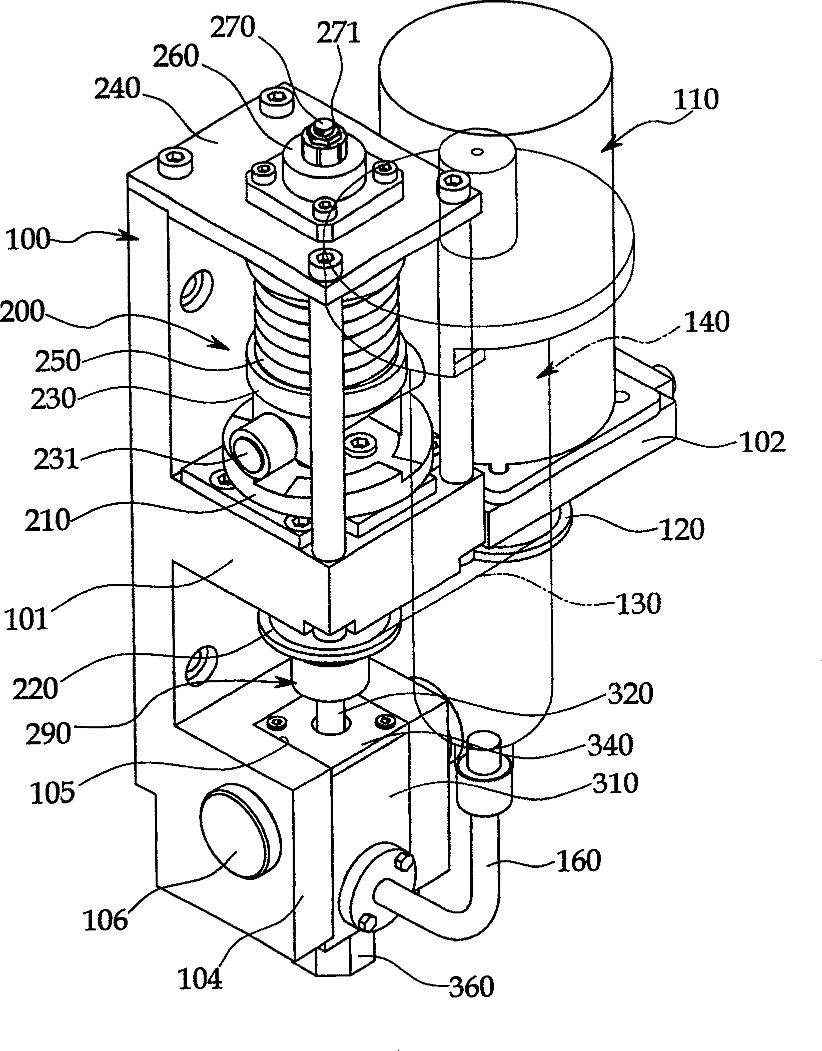
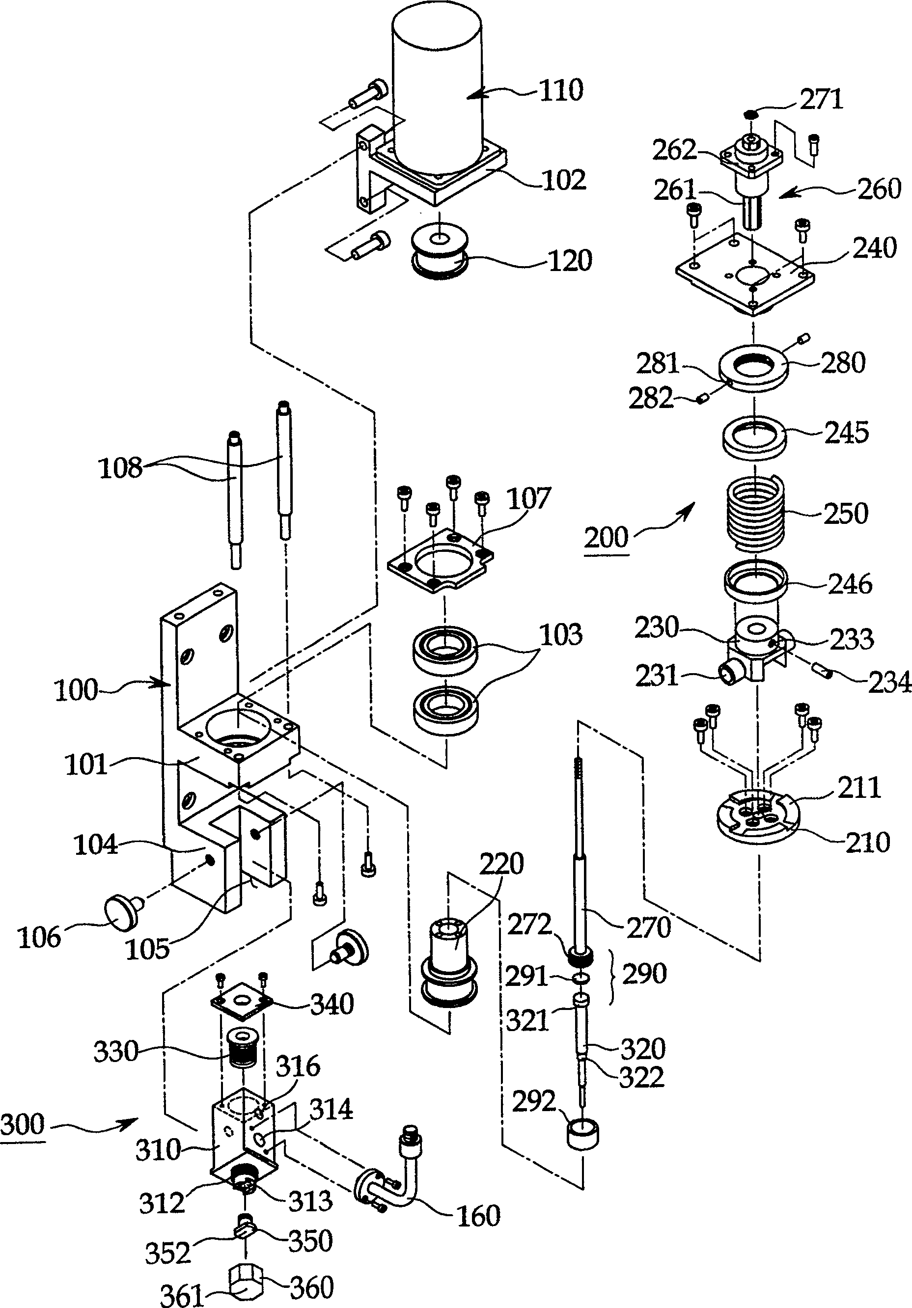
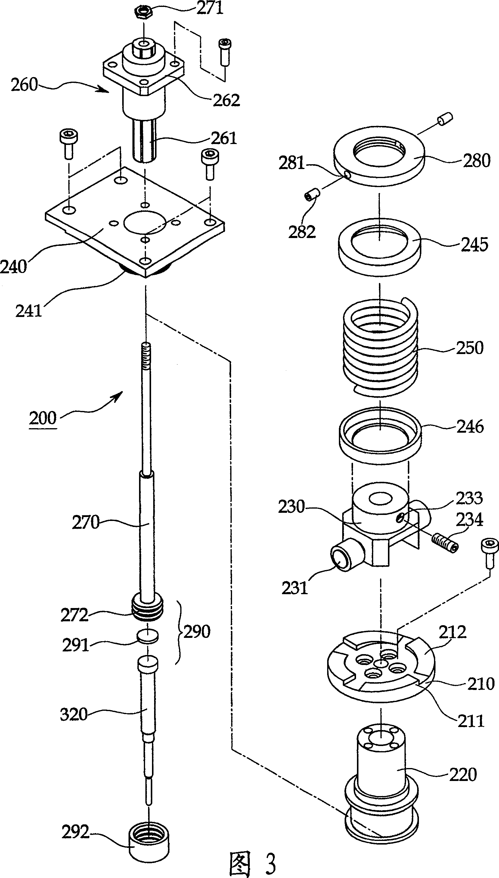
[0044] Such asfigure 1 ~As shown in Figure 6, the resin distributing device according to the present invention is installed on a common robot unit, including: a drive head main body 100 that can move along the X—Y—Z axis; A syringe 140 for resin storage; a servo motor 110 installed on one side of the main body 100; a vertical adjustment device 200 that receives the rotational force of the servo motor through a timing belt 130 and converts the rotational motion into a linear lifting motion; and has The dotting nozzle (dotting nozzle) 300 of the dotting rod 320 connected with the above-mentioned up and down adjustment device.

[0045] The drive head main body 100 is provided with a support bracket 102 on one side of the support platform 101 protruding from the middle, and the servo motor 110 is mounted on the support bracket 102 by bolts.

[0046] The structure of the a...


PUM


Abstract

Providing a resin dispensing device with a simple structure and to be adapted in various fields of applications, which allows easy assembly and integration with maintenance, replacement and component cleaning equipment, reduction of replacement cost, applications not related to resin and easy inspection of nozzle state, thereby optimizing reliability of the device. A resin dispensing device consisting of: a robotic assembly with conventional driving heads capable of moving along X-Y-Z axes; resin storage injection heads mounted to the driving heads of the robotic assembly so as to construct a resin dispensing device of configuration allowing dispensing of resin from the injection heads, characterized in: a top and a bottom adjustment means, the top and bottom adjustment means sustaining rotating forces of servo motor of a driving source provided at a side of the machine bed of the driving heads, converting the rotating forces into linear ascending and descending motions via camming effects, and causing variations in dispensing speed and route of the contact poles.

Description

technical field [0001] The present invention relates to a resin dispensing device for dispensing resins such as epoxy resins used for fixing components such as chips or ICs to printed circuit boards used in products such as home appliances and communication equipment (PCB), more specifically, the present invention relates to a resin dispensing device that has a simple structure and can be used in a variety of applications according to the applicable field, can perform maintenance and repair accompanying the use of the equipment, and the washing parts are easy to disassemble and assemble, saving Maintenance and repair costs, use regardless of the type of resin, and easy inspection of the state of the head, and greatly improve the reliability of the device. Background technique [0002] In general, in order to distribute viscous solutions (resins) such as epoxy resins for mounting surface mount components (chips, ICs) on printed circuit boards or to protect semiconductor eleme...

Claims


Application Information

Patent Timeline
Patent Type & Authority Patents(China)
IPC IPC(8): H05K3/30H01L21/58B05C5/00H01L21/56
CPCB65D1/40B65D21/086B65D23/003
Inventor 洪承珉李秀镇
Owner PROTEC CO LTD
Why Eureka
Try Eureka