
Evaporating fuel gas leak detection device

A gas leakage detection and detection device technology, which is applied in the direction of measuring devices, charging systems, engine components, etc., can solve the problems of long detection time, leakage, and long detection time of evaporative combustible gas

Inactive Publication Date: 2009-07-22
MITSUBISHI ELECTRIC CORP
View PDF7 Cites 0 Cited by
  • Summary
  • Abstract
  • Description
  • Claims
  • Application Information

AI Technical Summary

Problems solved by technology

[0006] The conventional evaporative combustible gas leakage detection device described in Patent Document 1 has the following situation: Since the leakage is judged by the internal pressure of the pressurized tank after introducing external air for a predetermined time, the suction and pressurization capacity of the pressurization device is limited. The error of the leakage affects the judgment of leakage, which reduces the judgment accuracy
In addition, the fuel tank is pressurized by using the injection pump used in the past to transfer the fuel from the sub chamber to the main chamber. This pressurization takes 100 to 130 seconds, and the detection time for evaporating combustible gas is long. As a result, the idling is not too long. In the case of
Since the pressure rise in the tank caused by the evaporation of the fuel itself is not taken into account, the judgment accuracy may also decrease due to this.
[0007] In the conventional evaporative combustible gas leakage detection device described in Patent Document 2, it is necessary to prepare in advance a judgment value table storing pressure rise values ​​assumed for various combinations of the air volume in the fuel tank and the fuel temperature, and a large capacity is required. memory for storage
In addition, since the determination value of the pressure rise value depends only on the air volume and fuel temperature, the determination accuracy may decrease due to the error in the content of low boiling point components in the fuel.
In addition, since the fuel tank is pressurized by the vapor pressure of the fuel itself with a weak pressurization pressure, the detection time is long, and the leakage detection is only performed when the generator is stopped, so the detection frequency is reduced

Method used


Image

  • Evaporating fuel gas leak detection device
  • Evaporating fuel gas leak detection device
  • Evaporating fuel gas leak detection device

Examples


Embodiment Construction

[0017] Embodiment 1

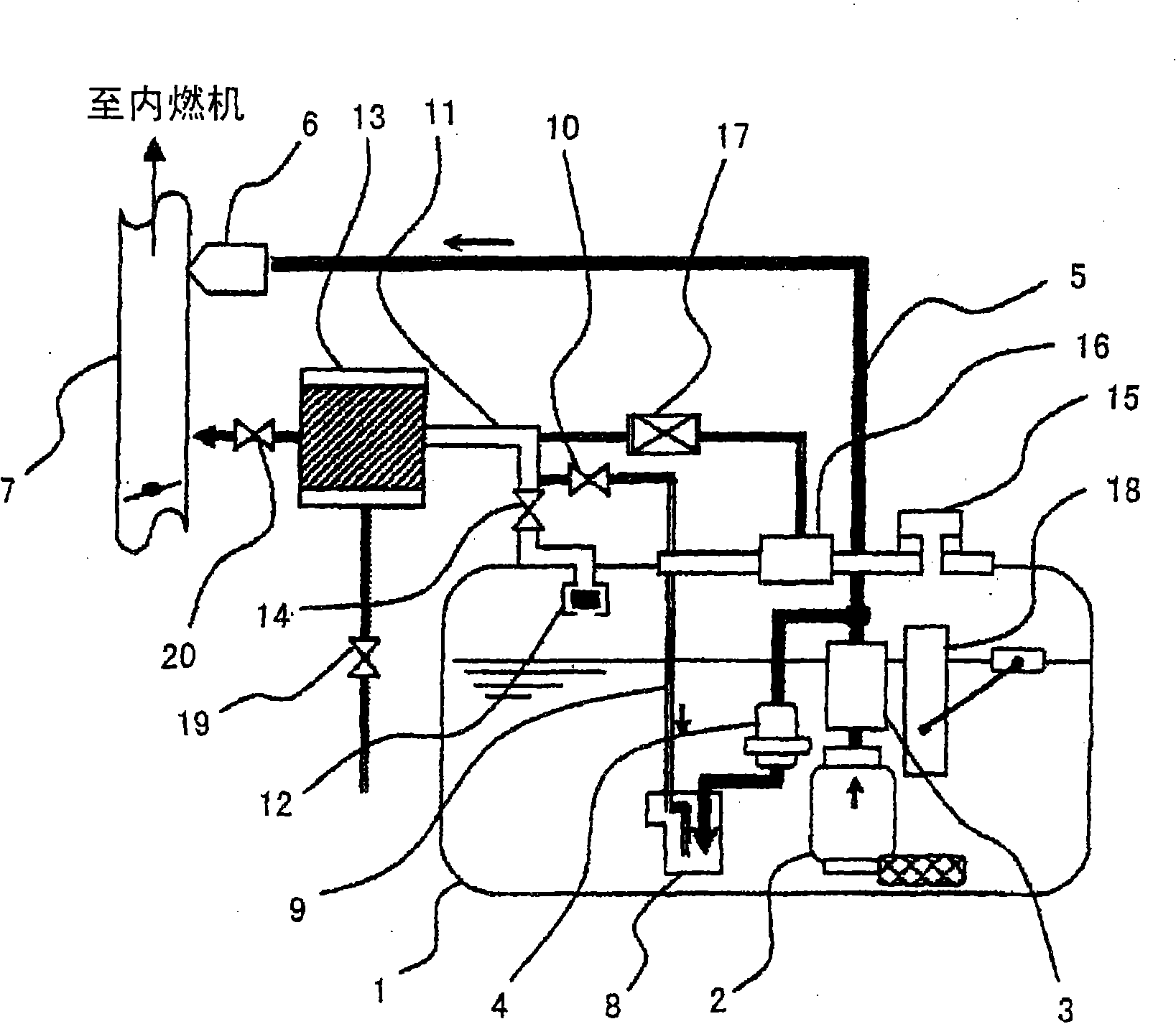
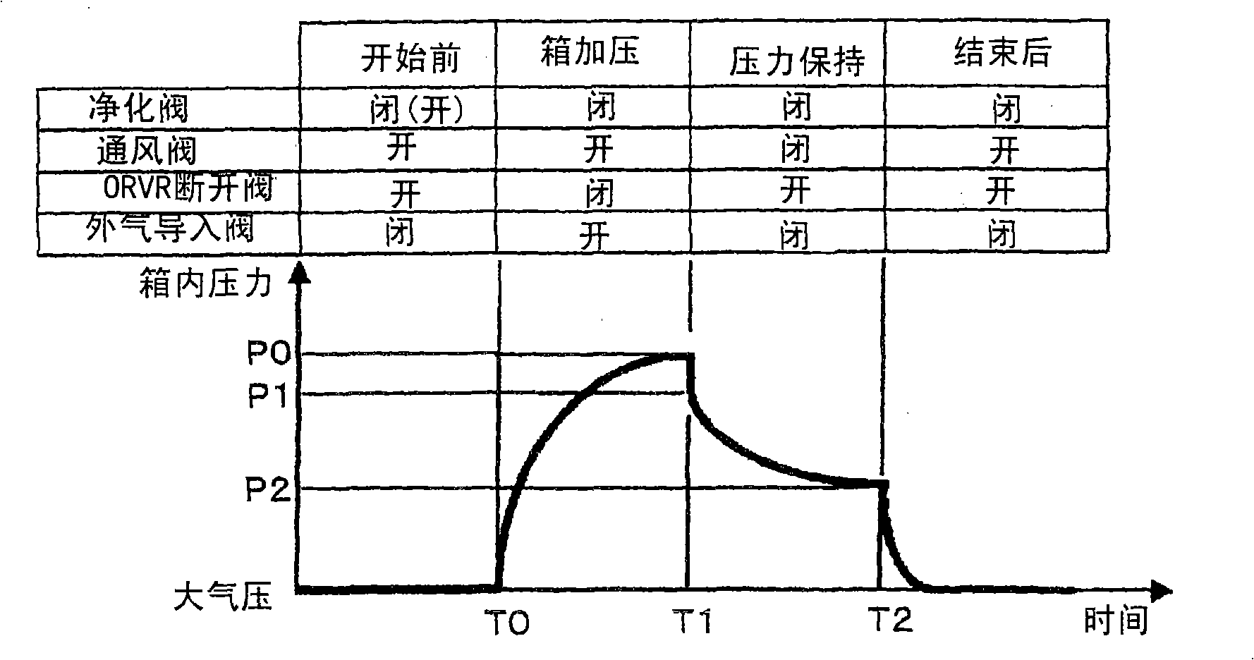
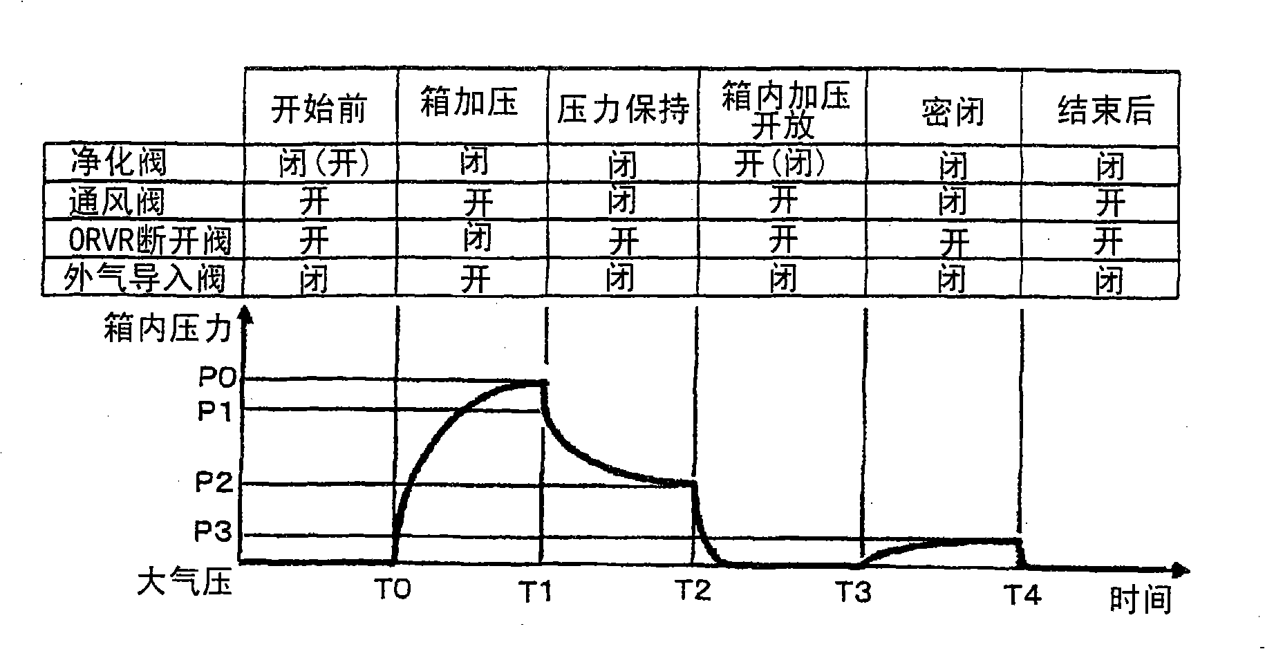
[0018] figure 1 It is a structural diagram of an evaporative combustible gas leakage detection device in Embodiment 1 of the present invention, figure 2 It is a graph showing the opening and closing sequence of the closing control valve of the evaporation purification system and the time change of the pressure in the fuel tank.

[0019] figure 1 In the fuel tank 1, the gasoline supplied from the fuel pump 2 is filtered by the fuel filter 3, adjusted to a certain pressure by the pressure regulator 4, supplied to the injector 6 through the fuel pipe 5, and injected from the injector 6 to The intake manifold 7 is then combusted in an internal combustion engine not shown.

[0020] An injection pump 8 serving as a pressurizing device in the fuel tank 1 is provided at a discharge port of the pressure regulator 4 branched from the fuel pipe 5 . One end of the outside air introduction pipe 9 is connected to the jet pump 8 , and the other end of the outside a...


PUM


Abstract

An evaporative combustible gas leakage detection device, in the leakage detection system of the evaporative purification system including the fuel tank (1) and the filter (13), has the following features: the return flow of the remaining fuel oil of the fuel oil sent to the internal combustion engine is used to introduce the atmosphere The injection pump (8) in the fuel tank (1); the internal pressure measurement device (15); and the fuel volume detection device (18), after the pressurization device carries out air supply for a specified time, the evaporation purification system is closed When the pressure maintenance measurement value is less than the decompression calculation value obtained from the pressurization measurement value, air volume and leakage hole diameter, it is judged as a leak.

Description

technical field [0001] The invention relates to a leakage detection device for vaporized combustible gas of a vehicle internal combustion engine. Background technique [0002] The conventional evaporative combustible gas leakage detection device described in Japanese Patent Document 1 has a structure that after the evaporative purification system is turned off during the operation of the internal combustion engine, after a predetermined period of time, outside air is introduced from the outside of the fuel tank and pressurized, Leakage is determined based on whether the measured internal pressure of the fuel tank reaches a set value. [0003] In addition, leak diagnosis is generally performed under stable operating conditions such as idling or low-speed operation in order not to be affected by changes in the operating conditions of the internal combustion engine. Therefore, to ensure detection accuracy, the measurement time needs to be long. However, in this case, According...

Claims


Application Information

Patent Timeline
Patent Type & Authority Patents(China)
IPC IPC(8): F02M25/08G01M99/00
CPCF02M25/0809F02M25/08
Inventor 吉冈浩三谷干城
Owner MITSUBISHI ELECTRIC CORP
Learn More