
A high power laser welding head

A high-power, laser technology, applied in the direction of laser welding equipment, welding equipment, metal processing equipment, etc., can solve the problems of laser lens damage, laser welding head burning, laser lens scrapping, etc., to achieve small maintenance, compact structure, welding smooth effect

Inactive Publication Date: 2009-08-12
SHENYANG DALU LASER COMPLETE EQUIP
View PDF5 Cites 0 Cited by
  • Summary
  • Abstract
  • Description
  • Claims
  • Application Information

AI Technical Summary

Problems solved by technology

[0003] However, there are certain deficiencies and deficiencies in the current high-power laser welding devices. The most important thing is that the laser welding head is close to the focus of the laser and close to the high temperature of the melting flame for a long time, so that the laser welding head is easily burned and lost. ability to weld
[0004] The main problem of the laser welding head commonly used at present is: the laser is directly projected on the workpiece, and the high-temperature ion cloud formed by ionization rises vertically to the laser lens and the strong laser reflection on the surface of the workpiece, which causes the laser lens to be damaged and lose its due performance.
What's more serious is that during the welding process, the high-temperature welding slag splashes everywhere, and it is easy to collapse and spray on the lens, which makes the expensive laser lens scrapped

Method used


Image

  • A high power laser welding head
  • A high power laser welding head
  • A high power laser welding head

Examples


Embodiment

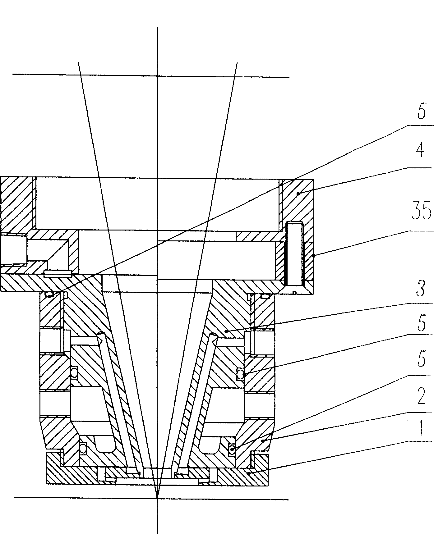
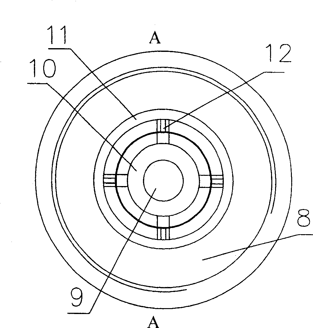
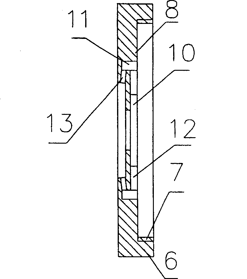
[0035] A high-power laser welding head includes a deflector 1, an outer sleeve 2, an inner sleeve 3, and a joint 4; the deflector 1 is disc-shaped, and a light-transmitting hole 9 is arranged in the center of the deflector 1, which is located outside the light-transmitting hole 9 An inner air ring 10 and an outer air ring 11 are provided, and the inner air ring 10 is connected to the lower end of the air channel 27 provided in the wall of the inner casing 3 .

[0036] The convex edge 6 around the disc-shaped deflector 1 is provided with an internal thread 7, which is threadedly connected with the external thread 15 provided at the lower end of the outer cover 2; The plane 8 and the upper plane 8 are in contact with the lower bottom surface 22 of the outer sleeve 2 and the inner sleeve 3, and a layer of heat-conducting silicone grease is coated on the contact surface to enhance the heat transfer efficiency and facilitate the cooling effect of the laser welding head.

[0037] Th...


PUM


Abstract

A high-power laser welding head includes a guiding plate, an outer cover, an inner cover and a joint, the circumference of the guiding plate is arranged with screw thread which is connected with the sole cover of the outer cover, the center of the guiding plate is arranged with a light-pervious hole, an inner air ring and an outer air ring, the inner air ring is connected with the outer air ring with an air course and is butt-jointed with the lower end of the air course of the inner cover, the outer air ring is communicated with one end of the nozzle and the other end of the nozzle is communicated with the light-pervious hole. The present invention has the advantages of reasonable designing, compact structure, convenient installing, little maintenance amount, simple operation, small heating effect of the laser welding head as the forced cooling of air cooling and water cooling are simultaneously provided, adapting for the long-time work, insulating the welding zone from the outer air as the strong-unreactive shielding gas is sprayed during operation, smooth welding, small welding seam width, small heat affected zone, high welding efficiency, good effect, completing the fine welding which can not realized in the traditional technique, and wide adopting industries, the invention can be adopted in various industries of machine manufacturing, rubber plastic product, petroleum chemical industry, watercraft and submarine manufacturing, water conservancy and electric power, aviation and spaceflight, apparatus and instrument, communication and artwork, etc.

Description

(1) Technical field [0001] The invention relates to parts of a laser welding machine, in particular to a high-power laser welding head. (2) Background technology [0002] With the development of science and technology, in recent years, laser technology has increasingly shown its superiority in welding, cutting and other processing techniques. The weld bead is smooth, the weld joint is fine in texture, and the overall welding quality is almost unmatched by other welding methods. Therefore, laser welding and cutting technology is increasingly recognized and adopted by people. [0003] However, there are certain deficiencies and deficiencies in the current high-power laser welding devices. The most important thing is that the laser welding head is close to the focus of the laser and close to the high temperature of the melting flame for a long time, so that the laser welding head is easily burned and lost. Ability to weld. [0004] The main problem of the laser welding head c...

Claims


Application Information

Patent Timeline
Patent Type & Authority Patents(China)
IPC IPC(8): B23K26/14B23K26/42B23K26/70
Inventor 陶兴启林青海
Owner SHENYANG DALU LASER COMPLETE EQUIP
Learn More