Eureka AIR delivers breakthrough ideas for toughest innovation challenges, trusted by R&D personnel around the world.

High accuracy three-dimensional rocker

A three-dimensional rocker, high-precision technology, applied in the field of rocker, can solve the problems of unable to adjust the lens, unable to meet the use requirements, incomplete images, etc., to achieve the effect of firm structure, easy assembly, and sensitive control

Inactive Publication Date: 2009-08-19
ZHE JIANG PEARMAIN ELECTRONICS
View PDF4 Cites 0 Cited by
  • Summary
  • Abstract
  • Description
  • Claims
  • Application Information

AI Technical Summary

Problems solved by technology

However, the existing joystick can only provide two-dimensional control. Although the position of the vehicle can be captured, the captured image is often too small or incomplete because of the inability to adjust the lens, which cannot meet the actual use requirements.

Method used


Image

  • High accuracy three-dimensional rocker
  • High accuracy three-dimensional rocker
  • High accuracy three-dimensional rocker

Examples


Embodiment 1

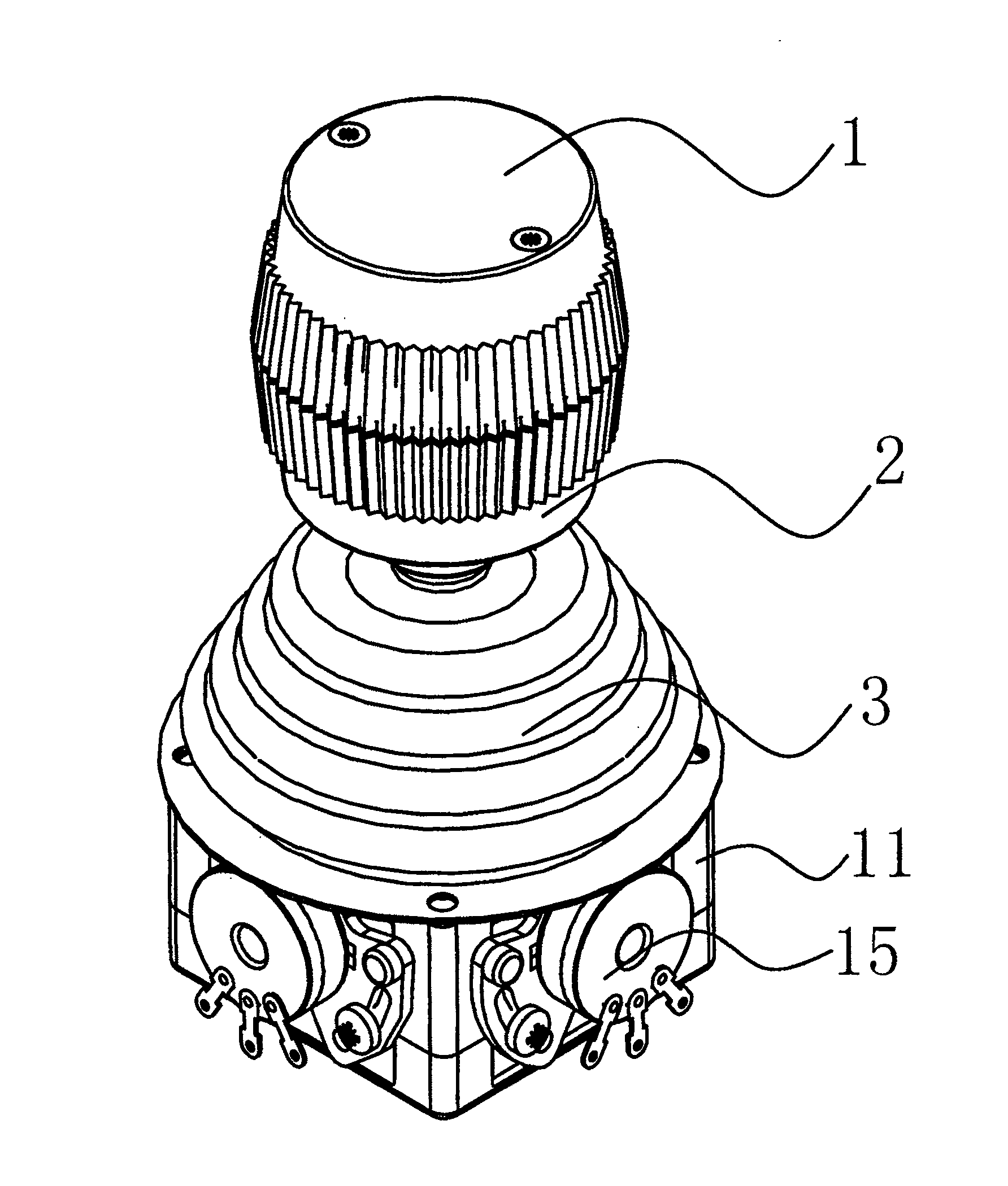
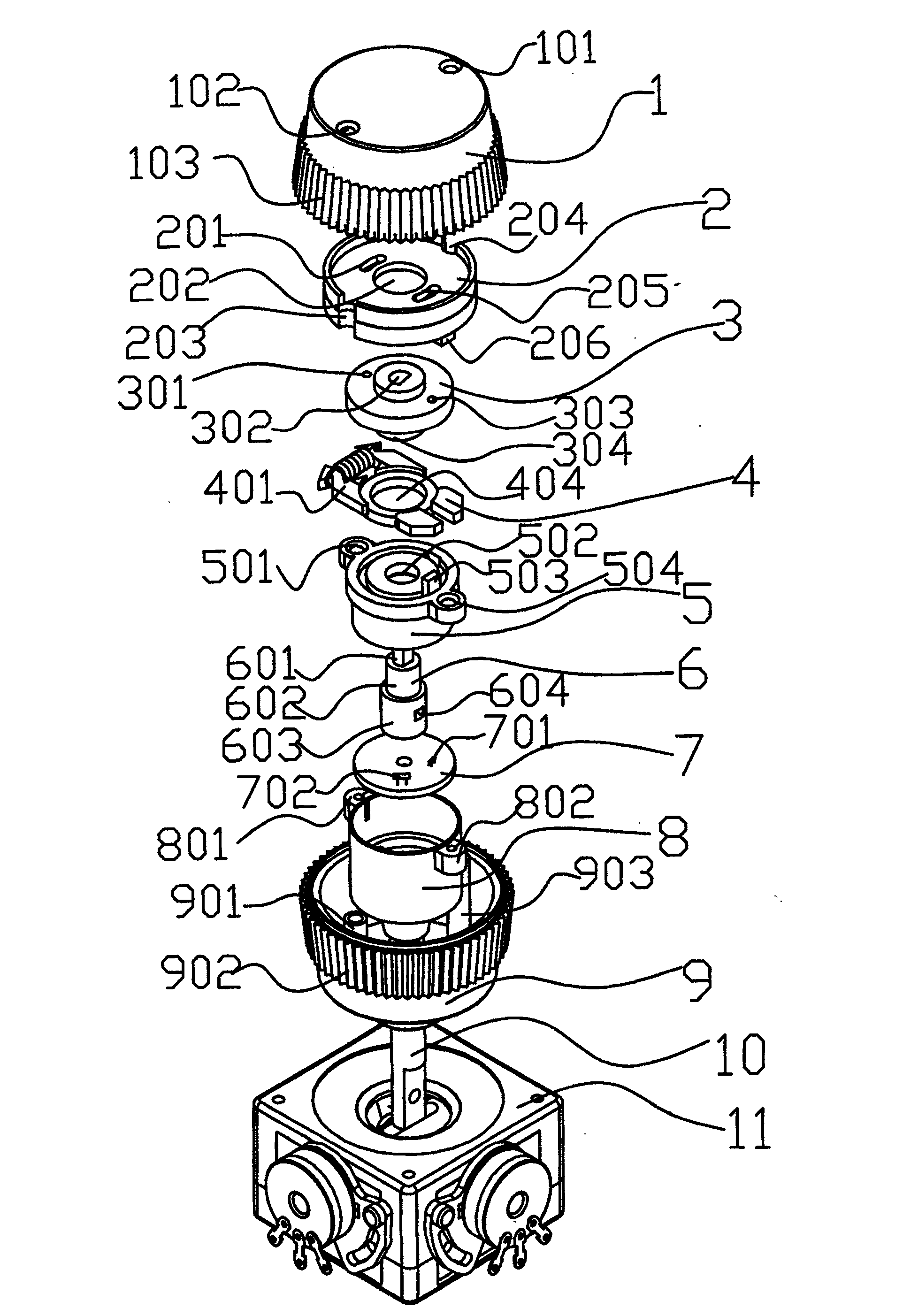
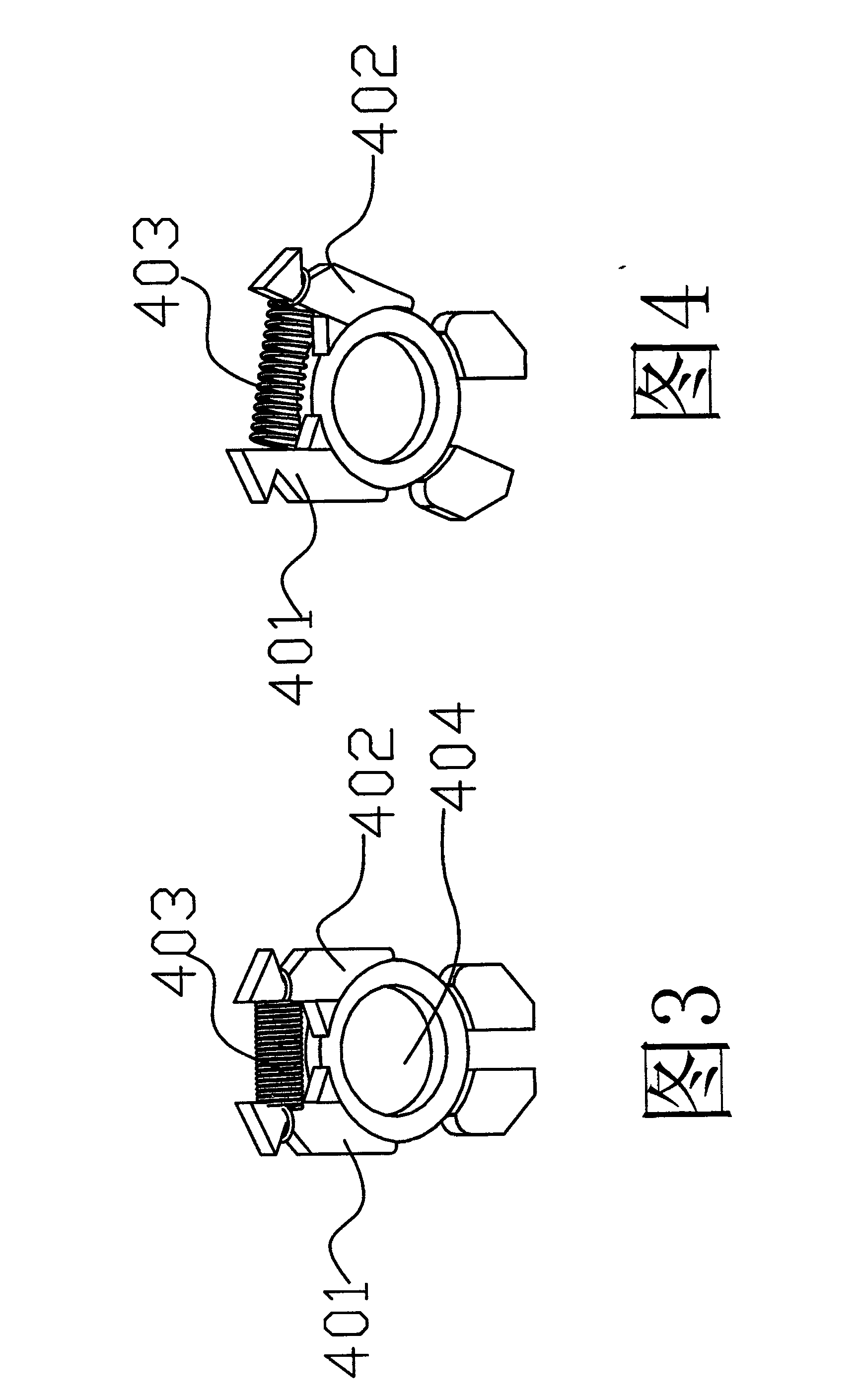
[0023] Embodiment 1: as figure 1 , 2 , 3, and 4, the high-precision three-dimensional rocker includes a base 1, a connecting rod 10 pierced on the base, and a first-direction action device and a second-direction action device installed in the base that are movably connected with the connecting rod 10. Device, the potentiometer 15 that is arranged on the outside of the base and is connected with the first direction action device and the second direction action device respectively (the first direction action device arranged in the base, the second direction action device are mentioned in the background technology in China Patent: 96249825.4 has been described in detail, and will not be described here.), the rocker handle at the other end of the connecting rod is provided with a third direction action device in the rocker handle, and the first The three-direction action device includes a connecting piece 2, a turntable 3, a reset device 4, a circuit board cover 5, a circuit boar...

Embodiment 2

[0032] Embodiment 2: as Figure 5 , 6 As shown, the difference between this embodiment and Embodiment 1 is that the high-precision three-dimensional rocker also includes a center automatic reset device, including a compression spring 12, a circular positioning block 13, and a conical surface 14 arranged on the base. , the positioning block is sleeved on the connecting rod 10, the compression spring 12 is located between the positioning block and the lower cover of the rocker handle, and a shield 12 is also provided outside the central automatic reset device.

[0033] When the rocker is under force, the state after moving is as follows Figure 5 As shown, the connecting rod moves, driving the circular positioning block to move, and the pressure spring shrinks. When the external force disappears, the compression spring naturally stretches, pushing the circular positioning block to move downward, because the circular positioning block is in contact with the conical surface on the ...


PUM


Abstract

The invention relates to a high-precision three-dimensional rocker, which includes a base, a connecting rod pierced on the base, a first-direction action device and a second-direction action device arranged in the base, which are movably connected with the link, and arranged on the base. The potentiometer connected to the first direction action device and the second direction action device on the outside, the rocker handle at the other end of the connecting rod, the third direction action device is arranged in the rocker handle, and the The action device in the third direction includes a reset device, a rotating shaft, and a Hall sensor circuit board; the beneficial effects of the present invention: the technical solution of the present invention realizes three-dimensional control without increasing the volume of the rocker, and this third The directional action device is easy to assemble, has a firm structure, stable performance, sensitive control, and high precision, and can be widely used in electromechanical equipment such as urban security, road monitoring, factory automation, electric power, finance, instrumentation, chemical industry, metallurgy, and medical imaging.

Description

technical field [0001] The invention relates to a rocker, in particular to a high-precision three-dimensional rocker. Background technique [0002] With the high development of industrial automation and artificial intelligence technology, it has become a reality that people can control the automation equipment to achieve their goals by standing in front of the terminal input device. As a terminal device, the joystick can manipulate the handle to output linear The control signal, combined with the control circuit to drive the stepper or servo motor, is deeply loved by users because of its humanized design and delicate control response. [0003] Using joysticks to control equipment has become a development trend in the contemporary automation field, but generally existing joysticks can only provide two-dimensional control, such as the highly sensitive and precise joystick described in Chinese patent: 96249825.4 , can only provide control in two directions, which can no longer...

Claims


Application Information

Patent Timeline
Patent Type & Authority Patents(China)
IPC IPC(8): G05G1/04
Inventor 王伟平潘民强
Owner ZHE JIANG PEARMAIN ELECTRONICS
Why Eureka
Eureka Blog
Learn More