
Laser processor

A laser processing machine and laser beam technology, applied in metal processing equipment, laser welding equipment, manufacturing tools, etc., can solve the problems of time-consuming, workpiece 2 damage, increase production cost, etc., to reduce production cost, ensure processing range, The effect of increasing the processing speed

Inactive Publication Date: 2009-09-09
CONTREL TECH CO LTD
View PDF6 Cites 0 Cited by
  • Summary
  • Abstract
  • Description
  • Claims
  • Application Information

AI Technical Summary

Problems solved by technology

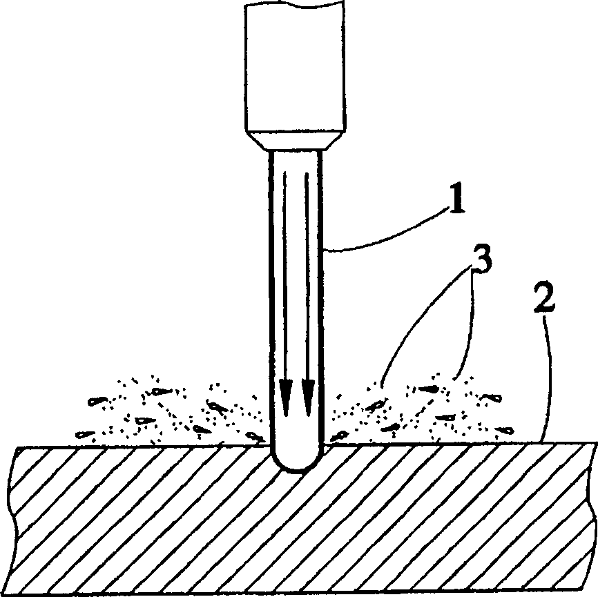
[0003] However, the existing processing machine uses an open high-pressure guiding water jet 1 for cutting. During the processing, it is easy to cause the water of the guiding water jet 1 to splash on the workpiece 2. After the workpiece 2 is cut, it must be cleaned and dried. The processing procedure has the disadvantages of time-consuming and increased production costs; moreover, the splashed water will carry the debris 3 produced by the workpiece 2 during the cutting process, causing scratches on the surface of the workpiece 2, or falling on the workpiece The workpiece 2 is damaged in the concave part, concave hole and groove of 2
In addition, if the protective film is applied before the workpiece 2 is cut, and then removed after the cutting is completed, although the debris 3 of the workpiece 2 can prevent the workpiece 2 from being damaged, it will cause cumbersome processing steps and increase the production cost. Shortcomings

Method used


Image

  • Laser processor
  • Laser processor
  • Laser processor

Examples


Embodiment Construction

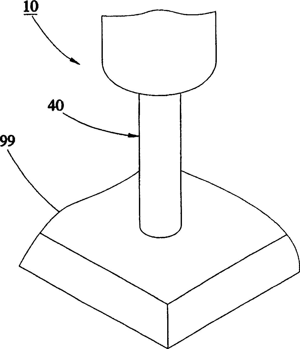
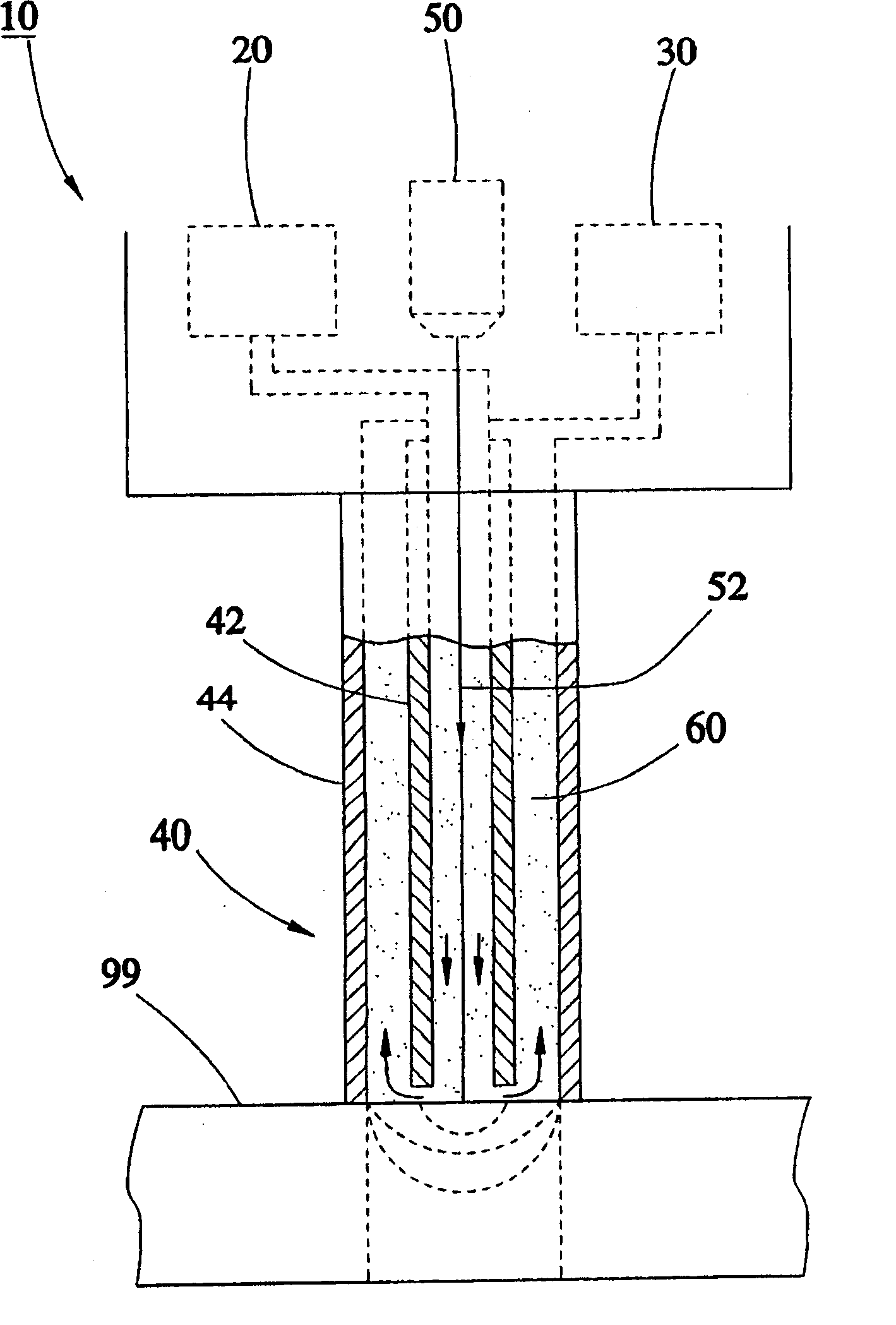
[0028] see Figure 2 to Figure 4 , the laser processing machine 10 provided by the first preferred embodiment of the present invention can process a workpiece 99, the laser processing machine 10 includes a supply device 20, a recovery device 30, an actuating device 40 and a laser device 50 .

[0029] The supply device 20 is used to output a fluid 60; wherein, the fluid 60 is selected from air, oxygen, carbon monoxide, carbon dioxide, nitrogen, inert gas, water or chemical liquid, and the chemical liquid is selected from One of the group consisting of sulfuric acid, hydrochloric acid, sodium nitrate, salts, sodium hydroxide, potassium hydroxide, and hydrofluoric acid. In this embodiment, the fluid 60 is selected as hydrochloric acid as an example.

[0030] The recovering device 30 is used for receiving the fluid 60 passing through the actuating device 40 and flowing through the workpiece 99 .

[0031] The actuating device 40 has a first guide part 42 and a second guide part 4...


PUM


Abstract

The laser processing machine includes one fluid providing unit; one fluid recovering unit; one actuating unit including one first guide part connected to the fluid providing unit and one second guide part connected to the fluid recovering unit; and one laser device to generate one laser beam penetrating the actuating unit and projected to the workpiece. In the laser processing machine, the fluid flowing through the first guide part and the laser beam process the workpiece simultaneously, and the fluid after processing the workpiece flow through the second guide part before being recovered in the fluid recovering unit.

Description

technical field [0001] The present invention relates to a processing machine, in particular to a processing machine which cuts with laser and uses fluid to assist processing. Background technique [0002] see figure 1 , the existing processing machine uses high-pressure guide water column 1 to form a commonly known as "water jet", by changing the impact position of guide water column 1, the workpiece 2 is processed, in order to achieve the purpose of cutting the workpiece 2 into a predetermined size. [0003] However, the existing processing machine uses an open high-pressure guiding water jet 1 for cutting. During the processing, it is easy to cause the water of the guiding water jet 1 to splash on the workpiece 2. After the workpiece 2 is cut, it must be cleaned and dried. The processing procedure has the disadvantages of time-consuming and increased production costs; moreover, the splashed water will carry the debris 3 produced by the workpiece 2 during the cutting proce...

Claims


Application Information

Patent Timeline
Patent Type & Authority Patents(China)
IPC IPC(8): B23K26/14B23K26/146
Inventor 郭佳李璧男郭佳
Owner CONTREL TECH CO LTD
Learn More