Planetary combined cylinder for belt conveyer

A conveyor belt and planetary technology, applied in the field of planetary combined rollers for conveyor belts, can solve the problems of large rotation resistance of idlers, bearing failure, high labor intensity, etc., shortening maintenance time, prolonging service life, and reducing labor. the effect of strength

Inactive Publication Date: 2009-12-02
唐群俊
View PDF4 Cites 0 Cited by
  • Summary
  • Abstract
  • Description
  • Claims
  • Application Information

AI Technical Summary

Problems solved by technology

[0002] The transportation of bulk materials widely used in metallurgy, chemical industry or mining industries is basically completed by conveyor belt conveyors. The driven rollers used on conveyor belt conveyors are such as tail wheels, surface increasing wheels, and counterweight redirecting wheels. etc., are all in the form of a single drum body. The disadvantage is that the drum must be replaced as a whole due to surface wear or bearing failure after a period of use. The replacement is labor-intensive and takes a long time, which affects production.
In addition, when the drum is working, the belt drives the entire drum to run, and the moment of inertia is large, thus wasting energy
[0003] The sealing structure of the existing idlers has two types: seal ring type and labyrinth type. The labyrinth seal is divided into radial labyrinth seal and axial labyrinth seal. The rotation resistance of the idler roller is very large

Method used


Image

  • Planetary combined cylinder for belt conveyer
  • Planetary combined cylinder for belt conveyer
  • Planetary combined cylinder for belt conveyer

Examples


Embodiment 1

[0023] Embodiment 1; Adopt rod type main shaft and rod type planet shaft:

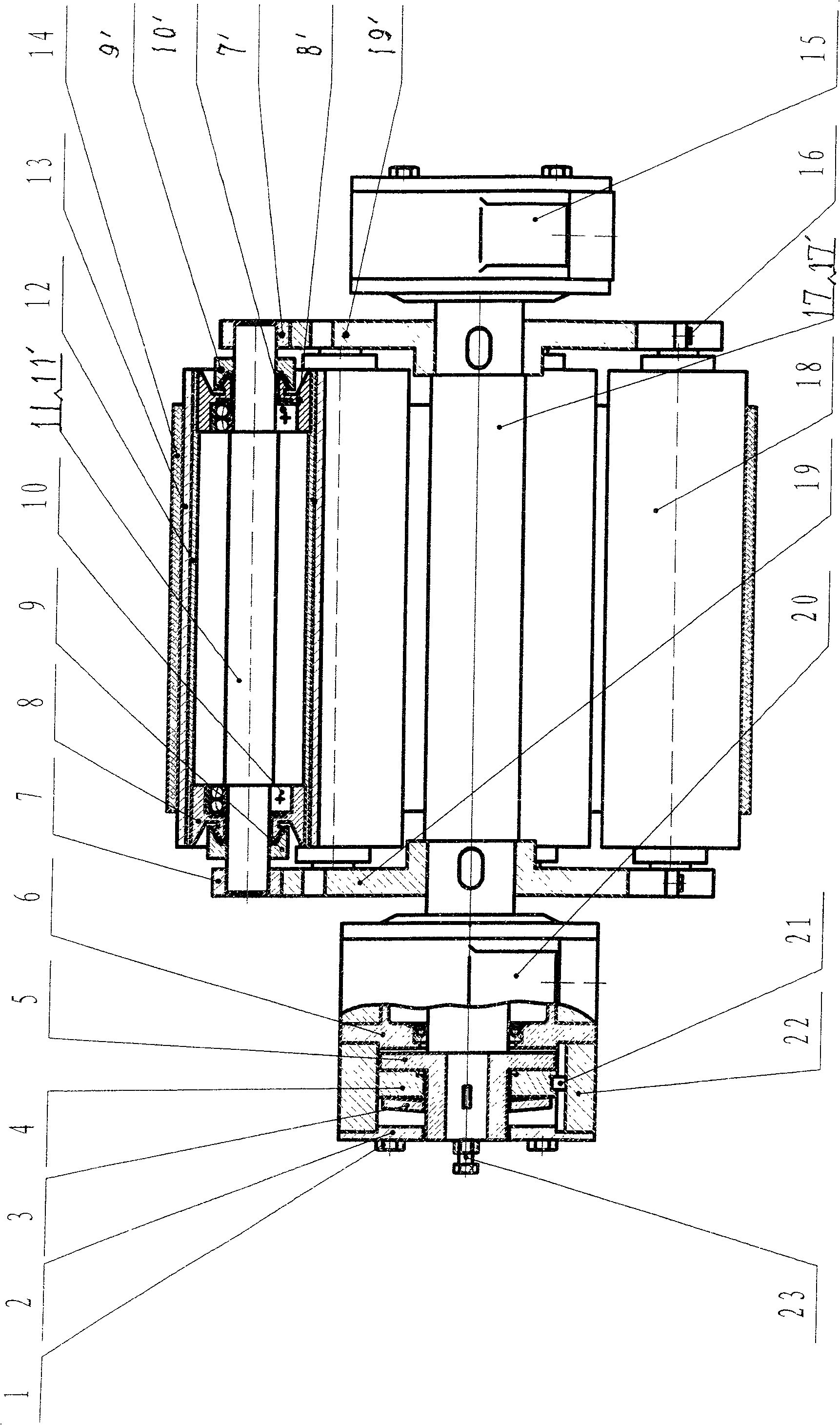
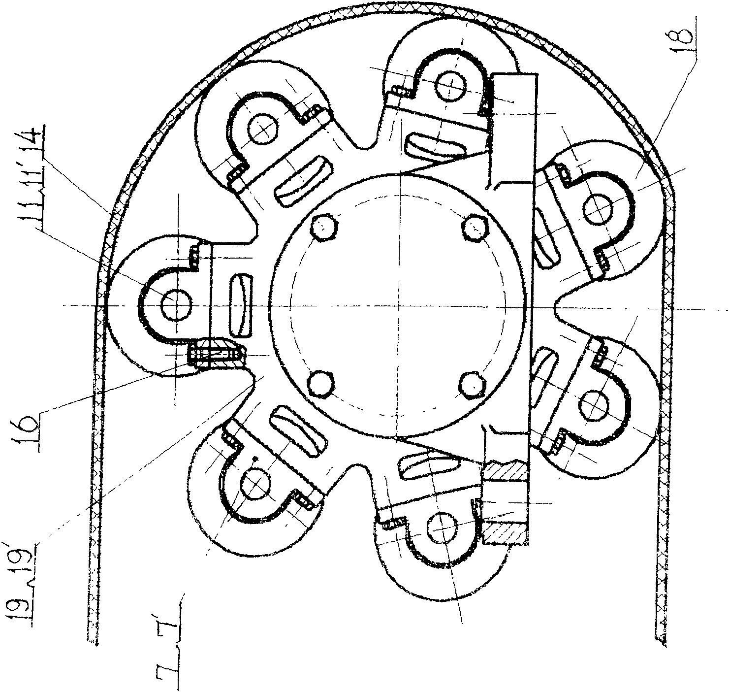
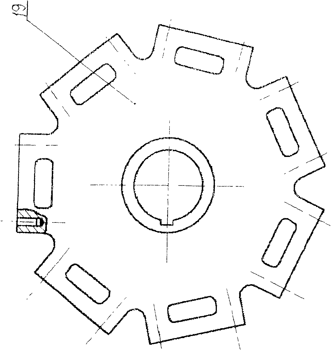
[0024] as attached figure 1 , figure 2 , image 3 , Figure 4 , Figure 6 and Figure 8 shown.

[0025] First assemble the rod type planetary roller 18, on the d segment and d' segment of the rod type planetary shaft 11 (such as Figure 6 ) is equipped with a left bearing 10 and a right bearing 10', close to the left bearing 10 and the right bearing 10', the left end cover 9 and the right end cover 9' are set on the d section and d' section of the rod type planetary shaft 11, the left bearing 10 and the The outer circumference of the left end cover 9 is fitted with a left bearing sleeve 8, the lower end of the left bearing sleeve 8 is processed with a tapered surface, and the two ends of the cone are processed with annular grooves 24, and the inner surface of the left end cover 9 is processed to match the left bearing sleeve 8. of the cone. Right bearing 10' and right end cover 9' are fitted w...

Embodiment 2

[0029] Embodiment 2, using tubular main shaft and tubular planetary shaft:

[0030] as attached figure 1 , figure 2 , image 3 , Figure 5 , Figure 7 and Figure 8 shown. From the rod-type main shaft 17 to the tube-type main shaft 17', from the rod-type planetary shaft 11 to the tube-type planetary shaft 11', the left planetary roller fixing seat 7 and the right planetary roller fixing seat 7' can also use sliding bearings seat or rolling bearing instead. Its structure and effect are identical with embodiment 1 description.


PUM


Abstract

The invention discloses a planetary combination roller for conveying belt conveyors used in metallurgy, mining, chemical industry and other industries to convey bulk materials. The left and right support plates are respectively assembled at both ends of the main shaft, and each planetary roller is equipped with a planetary roller fixing seat at both ends, and each planetary roller is assembled on the left , Right support plate. The two ends of the main shaft are equipped with left and right main shaft bearing seats. The second friction body is assembled on the shaft outlet end of the main shaft, and the first friction body and the disc spring are assembled on the extended section of the second friction body. The intermediate body is assembled between the disc cover and the transparent cover on the left main shaft bearing seat. The intermediate body, the disc cover and the transparent cover are screwed into the threaded holes on the left main shaft bearing seat by bolts passing through their positioning holes. The round key on the first friction body is embedded in the key groove of the intermediate body. The conveyor belt is only in contact with the outer surfaces of several planetary rollers. When some planetary rollers fail, the conveyor belt will automatically drive them to the non-working position. The combined roller is easy to replace and maintain, and has a long service life.

Description

technical field [0001] The invention relates to a roller, in particular to a planetary combination roller for a conveyor belt conveyor used in metallurgy, chemical industry or mining industry to convey bulk materials (such as coal powder, blast furnace slag or salt, etc.). Background technique [0002] The transportation of bulk materials widely used in metallurgy, chemical industry or mining industries is basically completed by conveyor belt conveyors. The driven rollers used on conveyor belt conveyors are such as tail wheels, surface increasing wheels, and counterweight redirecting wheels. etc., are all in the form of a single drum body. The disadvantage is that the drum must be replaced as a whole due to surface wear or bearing failure after a period of use. The replacement is labor-intensive and takes a long time, which affects production. In addition, when the drum is working, the belt drives the entire drum to run, and the moment of inertia is large, thereby wasting en...

Claims


Application Information

Patent Timeline
Patent Type & Authority Patents(China)
IPC IPC(8): B65G23/04B65G39/02
Inventor 吴建初唐群俊
Owner 唐群俊
Why Eureka
Try Eureka