
Flat-plate type broad frequency sensor for power transmission engineering

A flat-panel, sensor technology, applied in instruments, circuits, measuring electricity and other directions, can solve the problems of waveform distortion, large parasitic inductance, and no consideration of the reliability and long-term stability of sensor access sealing, so as to reduce parasitic inductance and improve The effect of the frequency response range

Active Publication Date: 2009-12-02
WUHAN HIGH VOLTAGE RESEARCH INSTITUTE OF STATE GRID
View PDF5 Cites 0 Cited by
  • Summary
  • Abstract
  • Description
  • Claims
  • Application Information

AI Technical Summary

Problems solved by technology

[0006] The purpose of the present invention is to solve the problem of the large parasitic inductance of the existing VFTO measuring flat sensor, the existence of the transition lead leads to the wave distortion caused by the refraction and reflection of the traveling wave, and the sealing reliability and long-term stability of the engineering for sensor access are not considered. For engineering practical problems such as sensor installation, built-in matching impedance, and integrated connection of coaxial signal transmission and shielding wires, a practical flat-panel broadband sensor for power transmission engineering is provided for online measurement of VFTO in GIS and H-GIS for UHV engineering Lay foundation; The present invention also can be applied to ultra-high voltage engineering VFTO measuring sensor, can be applied to partial discharge measurement and positioning sensor in GIS and H-GIS, can also be applied to GIS and H-GIS steady-state voltage (power frequency voltage ) sensor for measurement

Method used


Image

  • Flat-plate type broad frequency sensor for power transmission engineering
  • Flat-plate type broad frequency sensor for power transmission engineering
  • Flat-plate type broad frequency sensor for power transmission engineering

Examples


Embodiment Construction

[0020] The present invention will be described in further detail below in conjunction with the accompanying drawings.

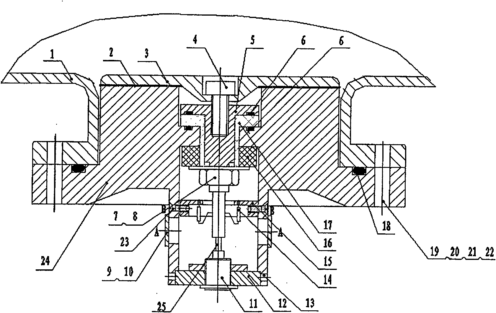
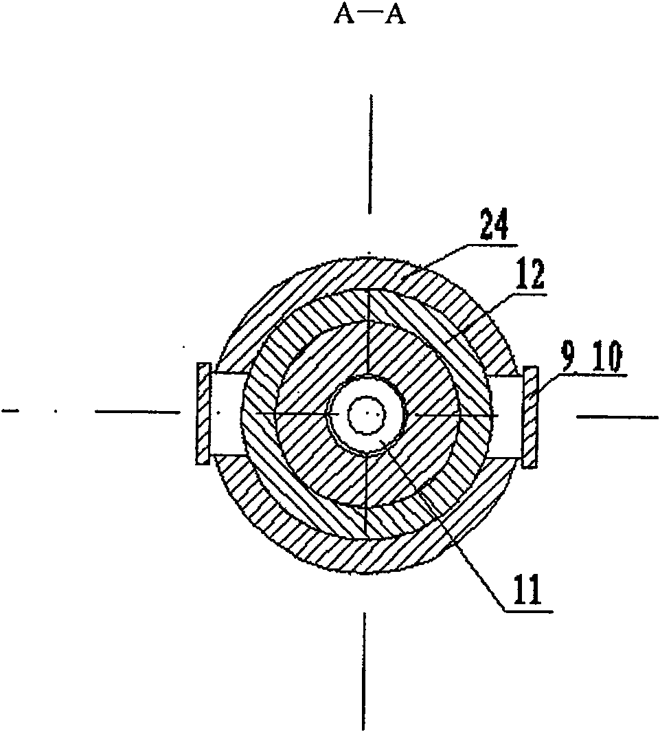
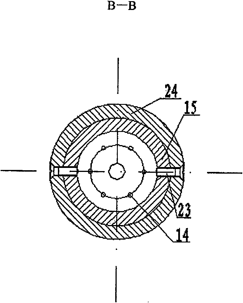
[0021] Figure 1-3 Instructions marked in: 1-GIS shell, 2-insulation film, 3-electrode plate, 4-sunk head bolt, 5-connector, 6-sealing ring, 7-nut, 8-washer, 9-shielding ring, 10-screw, 11-plug, 12-cover, 13-round head bolt, 14-matching resistor, 15-tray, 16-insulating sleeve, 17-insulating sleeve, 18-sealing ring, 19-bolt, 20-nut , 21-flat washer, 22-spring washer, 23-round head bolt, 24-cavity shielding, 25-connecting wire.

[0022] figure 1 It is a structural diagram of an embodiment of the present invention. The characteristic of the present invention is that the traditional sensor, the matching resistance of the measuring system, the signal shielding protection function and the connector connecting the measuring cable are integrated into one by using the capacitive voltage divider composed of the capacitive sensor.

[0023] The stray capacitance betw...


PUM


Abstract

A flat-panel broadband sensor for power transmission engineering, which includes a GIS shell 1, a cavity shield 24, an electrode plate 3, an insulating film 2, a connector 5, a plug 11, a tray 15, and a matching resistor 14; the cavity shield 24 is mounted on At the opening of the GIS housing 1, the electrode plate 3 is attached to the cavity shield 24 through the insulating film 2. The electrode plate 3 is electrically connected to the shielded plug 11 through the insulating connector 5, and the plug 11 is fixed on the cavity shield. 24, between the connector 5 and the plug 11, there is a tray 15 fixed in the inner cavity of the cavity shield 24, the axis of the plug 11 is located at the center of the tray 15, and a plurality of parallel matching Resistor 14. The invention is a practical fast steep wave sensor, which integrates the capacitive sensor, the matching resistance of the measurement system, the signal shielding protection function and the connection of the connector connecting the measurement cable, and a plurality of parallel matching resistances are evenly distributed on the sensor Internally, the measurement system has small parasitic inductance, small waveform distortion and wide measurement frequency domain, which can be used for VFTO measurement in GIS or H-GIS.

Description

technical field [0001] The invention belongs to a fast steep wave sensor for power transmission engineering, and is particularly suitable for on-line fast steep wave (VFTO) measurement of VFTO in UHV engineering equipment GIS and H-GIS, and can also be used for partial discharge measurement and power frequency voltage measurement. Background technique [0002] The operation of disconnectors in gas-insulated substations (GIS) and semi-gas-insulated substations (H-GIS) is very easy to generate fast steep overvoltage (VFTO) with high voltage amplitude and steep rise time. The higher the voltage level, the greater the harm of VFTO to GIS and H-GIS, especially for UHV projects. [0003] When the voltage level is low (such as 220kV, 500kV), in the actual project, the spherical capacitance probe packaged in the insulator is used as the sensor, and the supporting low-voltage arm capacitor is externally placed, and the external low-voltage arm capacitor and the auxiliary lead lead to...

Claims


Application Information

Patent Timeline
Patent Type & Authority Patents(China)
IPC IPC(8): G01R19/00G01R31/00H01H9/50
Inventor 王晓琪吴士普李璿林福昌叶国雄汪本进陈晓明鄢来君张国兵余春雨
Owner WUHAN HIGH VOLTAGE RESEARCH INSTITUTE OF STATE GRID
Learn More