Correlated measuring method for ion average velocity of orienting plasma beam

A technology of plasma and average velocity, applied in radiation measurement, measuring device, X/γ/cosmic radiation measurement, etc., can solve the problems of low precision, cumbersome measurement process, large error, etc. The effect of simple process

Inactive Publication Date: 2009-12-16
HARBIN INST OF TECH
View PDF0 Cites 0 Cited by
  • Summary
  • Abstract
  • Description
  • Claims
  • Application Information

AI Technical Summary

Problems solved by technology

[0007] The present invention provides a directional plasma injection method to solve the problems of large errors, cumbersome measurement process, low precision and inability to obtain the change characteristics of the ion average velocity in the order of microseconds in the existing method for measuring the average injection velocity of ions. Correlative measurement method of the average velocity of the ion in the body beam

Method used


Image

  • Correlated measuring method for ion average velocity of orienting plasma beam
  • Correlated measuring method for ion average velocity of orienting plasma beam
  • Correlated measuring method for ion average velocity of orienting plasma beam

Examples


specific Embodiment approach 1

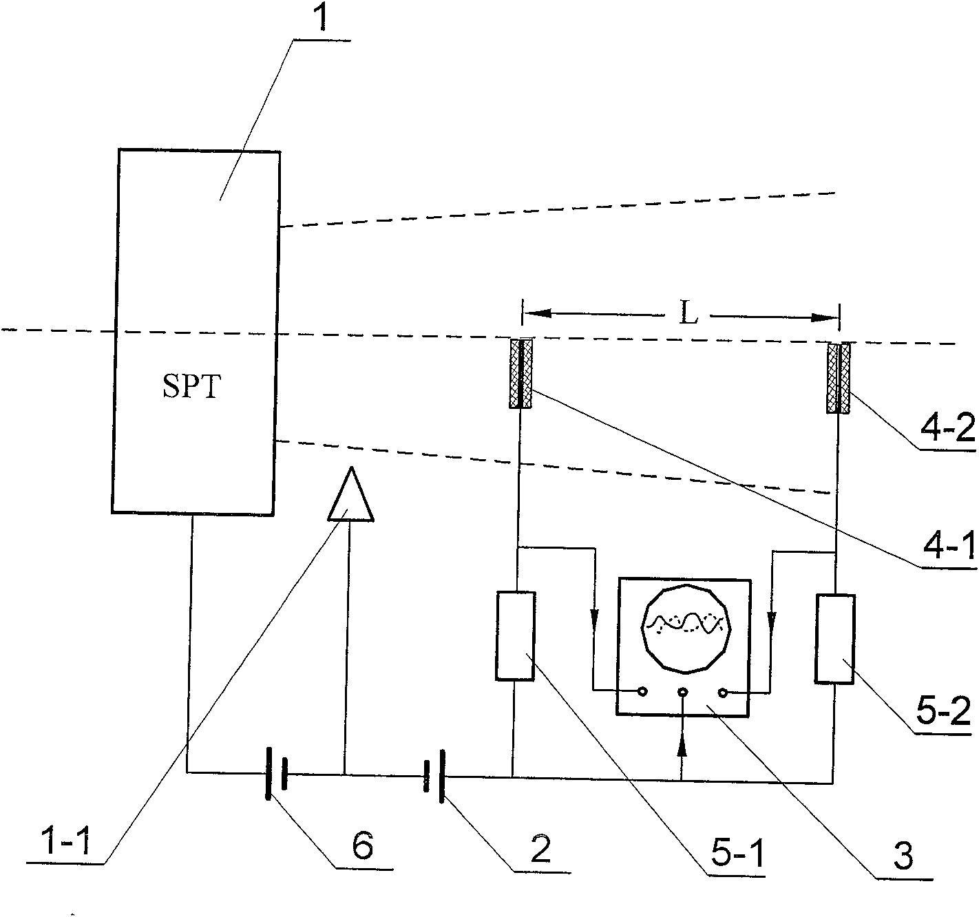
[0017] Specific implementation mode one: see figure 1 , figure 2 , the method for completing the present embodiment adopts a device with the following structure, which consists of a steady-state plasma engine 1, a positive bias power supply 2, an oscilloscope 3, a first probe 4-1, a second probe 4-2, Composed of resistance 5-1, second resistance 5-2 and power supply 6, the first probe 4-1 and the second probe 4-2 are respectively arranged in the plume area of ​​the steady-state plasma engine 1, the first probe The left and right central points of the upper end surfaces of the needle 4-1 and the second probe 4-2 are all located on the upper and lower central axes of the steady-state plasma engine 1, and the output end of the first probe 4-1 and the first resistor 5-1 The first end of the first end of the oscilloscope 3 is connected to the first input end of the oscilloscope 3, the output end of the second probe 4-2 and the first end of the second resistance 5-2 are connected ...

specific Embodiment approach 2

[0025] Specific implementation mode two: see image 3 , the difference between this embodiment and the first embodiment is that it is realized by the following steps:

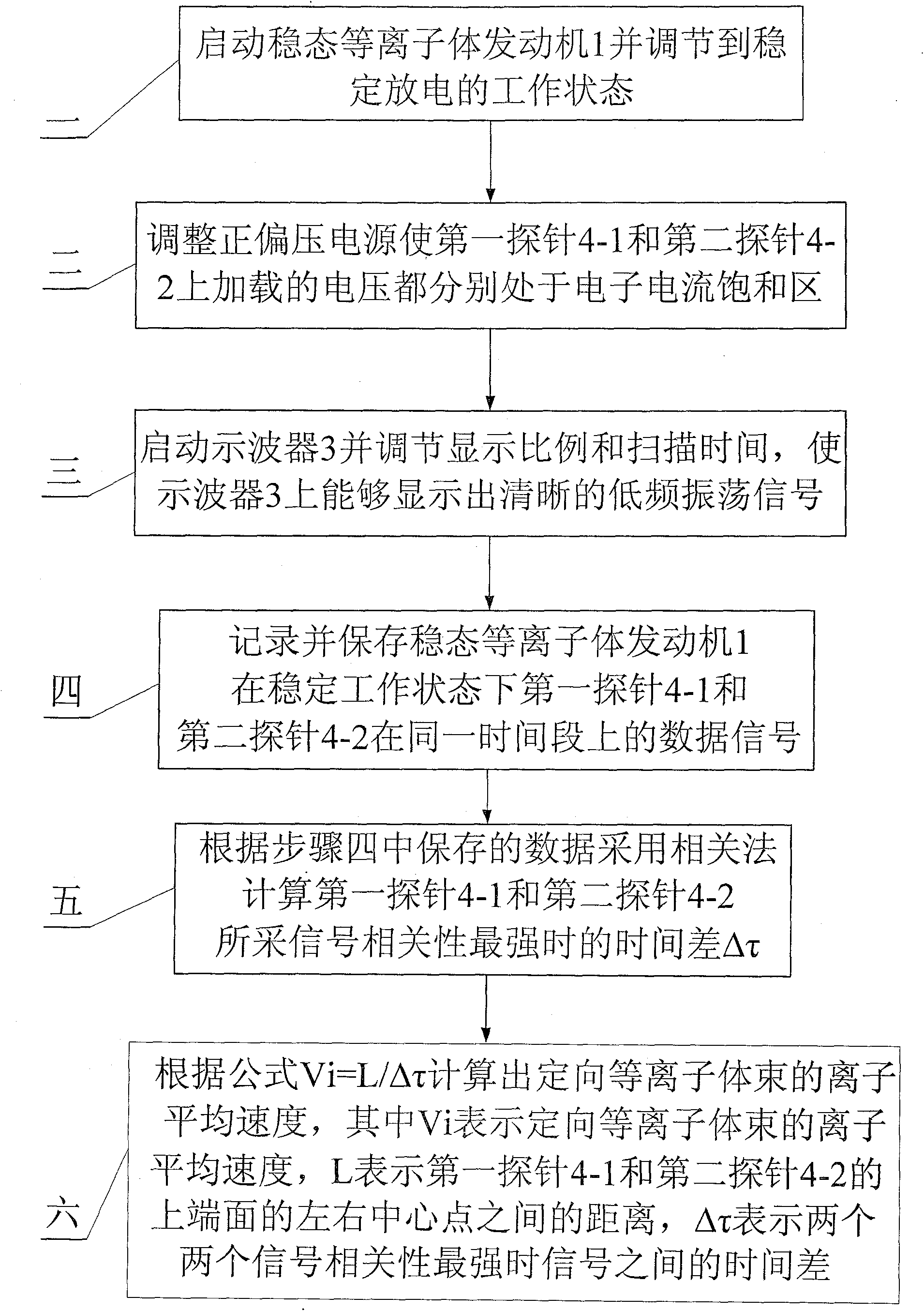
[0026] Step 1. Start the steady-state plasma engine 1 and adjust it to a stable discharge working state where the discharge voltage Up is 300V and the anode gas supply flow rate is 3mg / s. From then on, a certain density of plasma fills the plume area;

[0027] Step 2. Start the positive bias power supply 2. The positive bias power supply 2 can adopt a 0-100V adjustable DC stabilized power supply. Adjust the output value of the positive bias power supply 2 to 40V. The left and right central points are set at a distance of 15 cm from the upper and lower central points of the steady-state plasma engine 1, and the left and right central points of the upper end surface of the second probe 4-2 are arranged at a distance from the upper and lower central points of the steady-state plasma engine 1. The distance is 48cm...


PUM


Abstract

A related measurement method for the average velocity of directional plasma beam ions, which relates to a method for measuring the average velocity of directional plasma beam ions with density fluctuation characteristics, in order to solve the problems of existing measurement methods such as large errors, cumbersome measurement process, inability to The problem of obtaining the average velocity change characteristics of ions on the order of microseconds. The method of the present invention consists of the following steps: Step 1, start the steady-state plasma engine and adjust to a stable discharge state; Step 2, adjust the positive bias power supply so that the voltages loaded on the two probes are respectively in the electron current saturation region Step 3, start the oscilloscope, adjust and make it possible to display a clear low-frequency oscillation signal on the oscilloscope; Step 4, record the data signals of the two probes in the same time period of the steady-state plasma engine in a stable working state; Step 5 1. Find the time difference when the correlation between the signals of the two probes is the strongest; Step 6. Calculate the ion average velocity of the directional plasma beam according to the formula Vi=L / Δτ.

Description

technical field [0001] The invention relates to a method for measuring the average velocity of ions in a directional plasma beam with density fluctuation characteristics. Background technique [0002] Oriented plasma beams have been widely used in the fields of etching and aerospace propulsion. The average ejection velocity of ions is one of the important indicators of oriented plasma, but its measurement has always been a difficult problem, especially its dynamic characteristics. [0003] Steady-state plasma engine (SPT) is a kind of electric propulsion device, which is widely used in high-orbit satellite attitude maintenance, orbit transfer, deep space exploration and other fields. SPT heats electrons by an electric field to ionize an inert gas as a working medium, and the formed plasma is accelerated by an electric field to form a high-speed directional plasma jet, and its specific impulse (that is, the average ejection speed of ions relative to the device) can reach 2000...

Claims


Application Information

Patent Timeline
Patent Type & Authority Patents(China)
IPC IPC(8): G01T1/29H01J37/244
Inventor 宁中喜于达仁李鸿刘辉丁永杰
Owner HARBIN INST OF TECH
Why Eureka
Try Eureka