Hydraulic tyre vulcanizing machine in column type strap clamp locked mould mode, and method for adjusting mould

A tire vulcanization and vulcanizing machine technology, applied in tires, other household appliances, household appliances, etc., can solve the problems of poor positioning and guidance, reduced weight of the whole machine, and large maintenance of mechanical structure, so as to reduce manufacturing costs and use maintenance. cost, improve tire vulcanization quality, and reduce maintenance workload

Active Publication Date: 2009-12-23
SINO ARP TIRES EQUIP TECH (SUZHOU) CO LTD
View PDF5 Cites 2 Cited by
  • Summary
  • Abstract
  • Description
  • Claims
  • Application Information

AI Technical Summary

Problems solved by technology

[0003] The mechanical tire vulcanizing machine generally adopts a four-bar linkage mechanism. It uses the four-bar linkage mechanism to perform mechanical movement to realize the tightness of the upper and lower molds. After pressurization and heating, the tire is vulcanized in the mold. Its disadvantages are as follows: The structure is complex, such as the beam base structure is bulky, and includes a crank gear transmission mechanism, etc.; the second is poor rigidity, such as the beam and the four-link are easily deformed; the third is the centering accuracy is low; the fourth is that the mold life is long due to the deformation of the beam Affected; Fifth, the long time of mold opening and closing affects the efficiency; Sixth, the maintenance of the mechanical structure is large
Although such a structural form can save parts such as the frame and reduce the weight of the whole machine, due to the addition of parts such as the upper and lower cylinders and lock rings, the mold is surrounded by the upper and lower cylinders, resulting in difficulty in connection and inconvenient maintenance.
Secondly, the mold adjustment mechanism is realized by the mold adjustment cylinder installed in the abdominal cavity of the base. The mold adjustment cylinder must directly bear the mold clamping force and is connected with the pressurized cylinder, which makes the structure of the two cylinders complex and large, difficult to maintain, and also makes the mold Multiple cylinders cannot be installed, so that the pressure on the mold cannot be more uniform
Third, due to the form of a single column for mold opening and closing, the column is placed behind the middle of the vulcanizing machine, resulting in uneven force on the column, poor positioning and guidance, and unstable operation, which affects the accuracy of the whole machine, especially the repeatability

Method used


Image

  • Hydraulic tyre vulcanizing machine in column type strap clamp locked mould mode, and method for adjusting mould
  • Hydraulic tyre vulcanizing machine in column type strap clamp locked mould mode, and method for adjusting mould
  • Hydraulic tyre vulcanizing machine in column type strap clamp locked mould mode, and method for adjusting mould

Examples


Embodiment 1

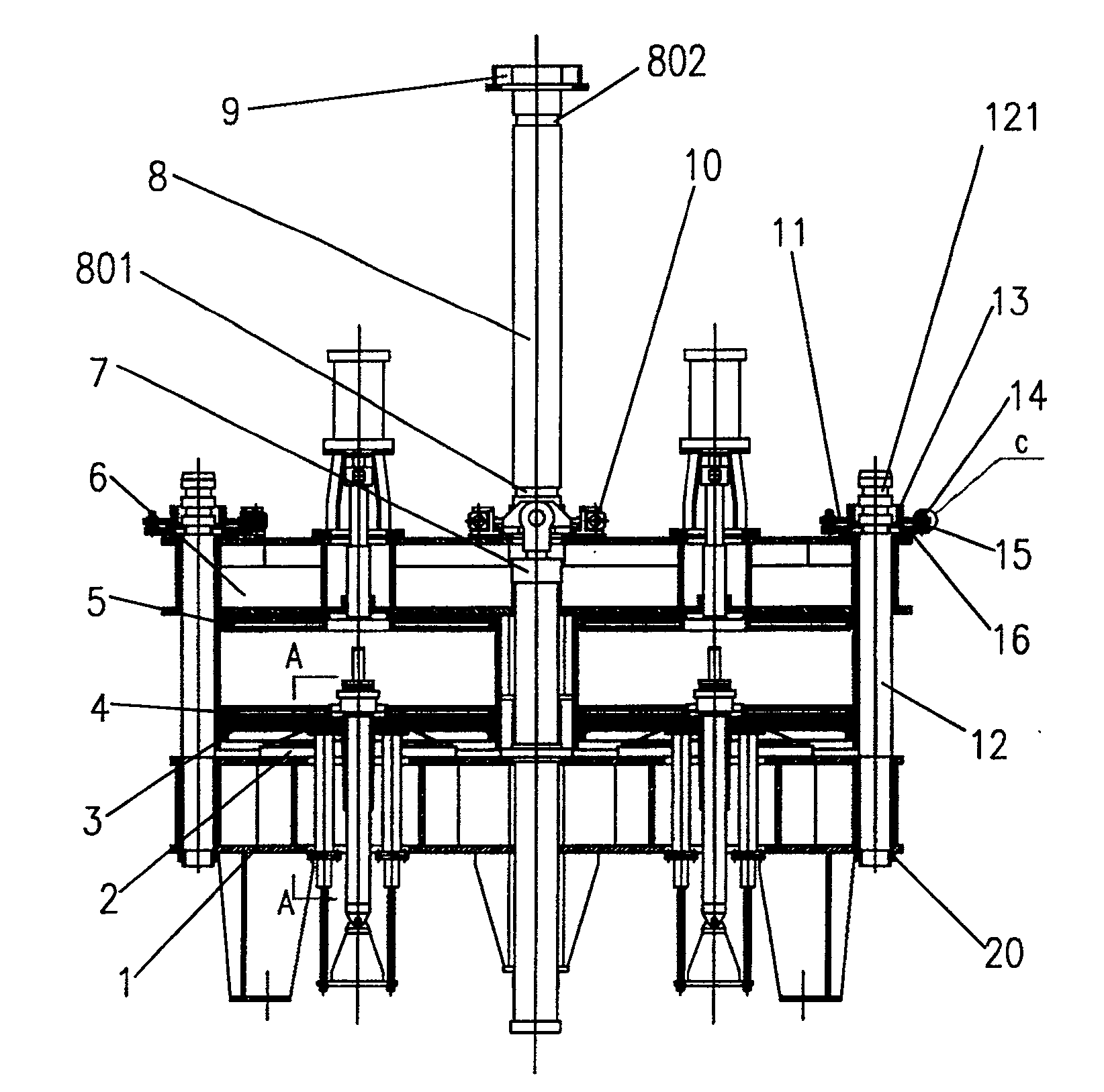
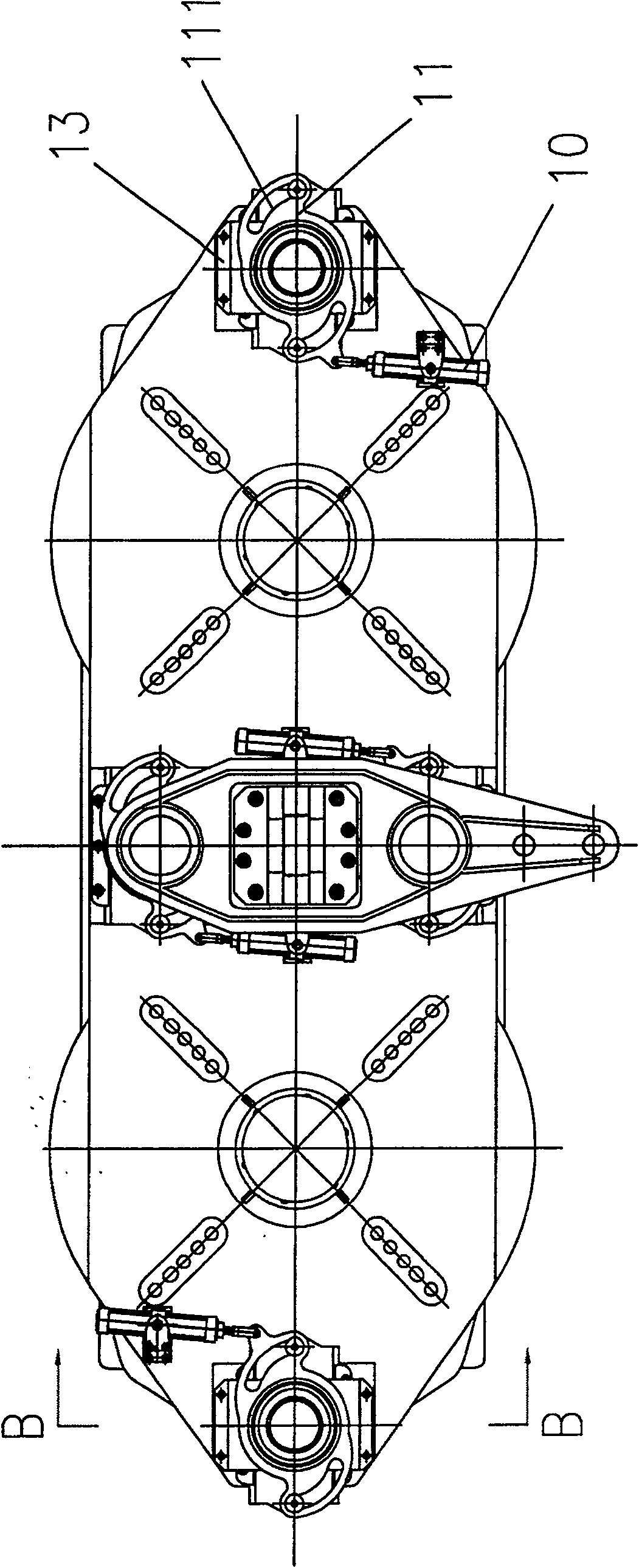
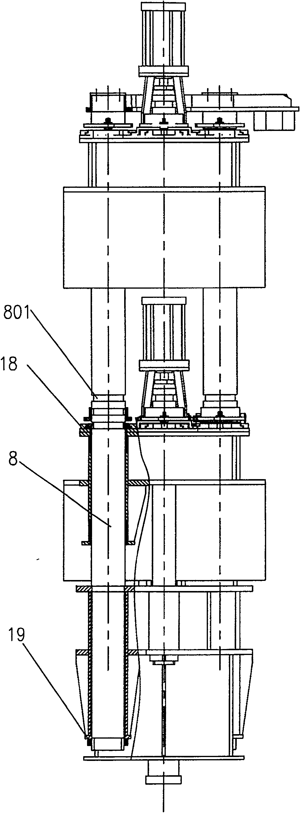
[0037] Embodiment one, see Figure 1 to Figure 6 As shown, a hydraulic tire vulcanizer with a column clamp lock mode of the present invention is a hydraulic tire vulcanizer with a double-column double-mode structure, which includes a base 1, a plurality of pressurized oil cylinders 2, and a lower supporting plate 3, which can be used for mounting The upper hot plate 5 and the lower hot plate 4 connected to the upper and lower molds of the tire mold, the upper beam that can be lifted and lowered 6, the mold opening and closing cylinder 7, the column 8 used to guide the mold opening and closing and bear the clamping force, the upper bracket 9, Auxiliary column 12 and pallet type mold clamping device; pallet type mold clamping device includes clamping cylinder 10, clamping cam 11, cam bracket 13, clamping bearing 14, small shaft 15, clamping platen 17 and can be connected with column or auxiliary column The clamping plate 16 engaged with the annular groove.

[0038] Among them, ...

Embodiment 2

[0049] Embodiment two, see Figure 7 , Figure 8 As shown, a hydraulic tire vulcanizing machine with column clamp lock mode of the present invention is a four-column double-mode hydraulic tire vulcanizing machine, which is different from Embodiment 1 in that it consists of two opening and closing molds arranged The oil cylinder 7 replaces the one in the first embodiment, and the two uprights and the two auxiliary uprights in the first embodiment are replaced by four uprights 8 arranged at the four corners of the machine.

Embodiment 3

[0050] Embodiment three, see Figure 9 As shown, a hydraulic tire vulcanizing machine with column clamp lock mode of the present invention is a six-column double-mode hydraulic tire vulcanizing machine. Die oil cylinder 7 replaces one of embodiment one, and replaces two uprights and two auxiliary uprights of embodiment one by six uprights 8 arranged at the four corners of the machine and the front and rear sides of the middle part.


PUM


Abstract

The invention discloses a hydraulic tire vulcanizing machine with column clamping plate lock mode and its mold adjustment method, which comprises a base, a liftable upper beam, a column for guiding mold opening and closing and bearing mold clamping force, an oil cylinder for opening and closing molds, Pressurized oil cylinder, lower supporting plate, upper and lower heating plates for mounting and connecting the upper and lower molds of the tire mold, and clamping mold clamping device. Through the loose / clip fit between the clamping plate and the annular groove of the column, a closed force system of the clamping force is formed, and the clamping force is applied, and components such as the frame, the upper and lower cylinders, and the locking ring can be omitted, so that the structure of the vulcanizing machine is simple. Reliable and easy to maintain. Due to the adoption of a unique mold clamping system, mold adjustment method, pressurized oil cylinder installation method, and multi-column guiding structure, the overall structure of the hydraulic tire curing machine can be greatly simplified, the height and weight of the whole machine are greatly reduced, and the amount of maintenance is greatly reduced. Reduced, thereby improving the precision of the hydraulic tire vulcanizing machine and greatly reducing the manufacturing cost.

Description

technical field [0001] The invention relates to a tire vulcanizing equipment, in particular to a hydraulic tire vulcanizing machine in a column clamping plate lock mode and a mold adjustment method thereof. Background technique [0002] Tire curing presses are usually divided into two categories: mechanical and hydraulic. [0003] The mechanical tire vulcanizing machine generally adopts a four-bar linkage mechanism. It uses the four-bar linkage mechanism to perform mechanical movement to realize the tightness of the upper and lower molds. After pressurization and heating, the tire is vulcanized in the mold. Its disadvantages are as follows: The structure is complex, such as the beam base structure is bulky, and includes a crank gear transmission mechanism, etc.; the second is poor rigidity, such as the beam and the four-link are easily deformed; the third is the centering accuracy is low; the fourth is that the mold life is long due to the deformation of the beam Affected; ...

Claims


Application Information

Patent Timeline
Patent Type & Authority Patents(China)
IPC IPC(8): B29C35/02B29C33/30B29L30/00
Inventor 陈强
Owner SINO ARP TIRES EQUIP TECH (SUZHOU) CO LTD
Why Eureka
Try Eureka