
Detecting instrument on capillary electrophoresis-multi-photon excitation fluorescent column

A capillary electrophoresis and multi-photon technology, applied in the field of high-sensitivity multi-photon fluorescence detection, can solve the problems of difficult secondary focusing, poor repeatability, and sensitivity effects, thereby simplifying experimental equipment and experimental operations, reducing the cost of experimental equipment, and simplifying the column. The effect of the post-detection method

Inactive Publication Date: 2009-12-23
HUAZHONG UNIV OF SCI & TECH
View PDF4 Cites 0 Cited by
  • Summary
  • Abstract
  • Description
  • Claims
  • Application Information

AI Technical Summary

Problems solved by technology

The difficulties in post-column detection are: i), there is a focus point problem in post-column detection, and the focus of the objective lens is aligned with the center of the capillary outlet, and CCD detection is used, which increases the equipment cost of the detection system, and the experimental operation becomes complicated; ii) 1. There is a problem of debris accumulation in the post-column detection. The substances flowing out of the capillary in the experiment are easy to accumulate at the detection window, which is not conducive to excitation and fluorescence detection; iii) There is a cleaning problem in the post-column detection. Since one end of the capillary is the detection window, This complicates the cleaning of the capillary, and the detection end of the capillary must be moved to the cleaning pool, resulting in secondary focusing problems
In short, the traditional detection device adopts complex post-column detection, the experimental operation is cumbersome, the cost is high, and the repeatability is poor, and the sensitivity is also affected

Method used


Image

  • Detecting instrument on capillary electrophoresis-multi-photon excitation fluorescent column
  • Detecting instrument on capillary electrophoresis-multi-photon excitation fluorescent column
  • Detecting instrument on capillary electrophoresis-multi-photon excitation fluorescent column

Examples


example

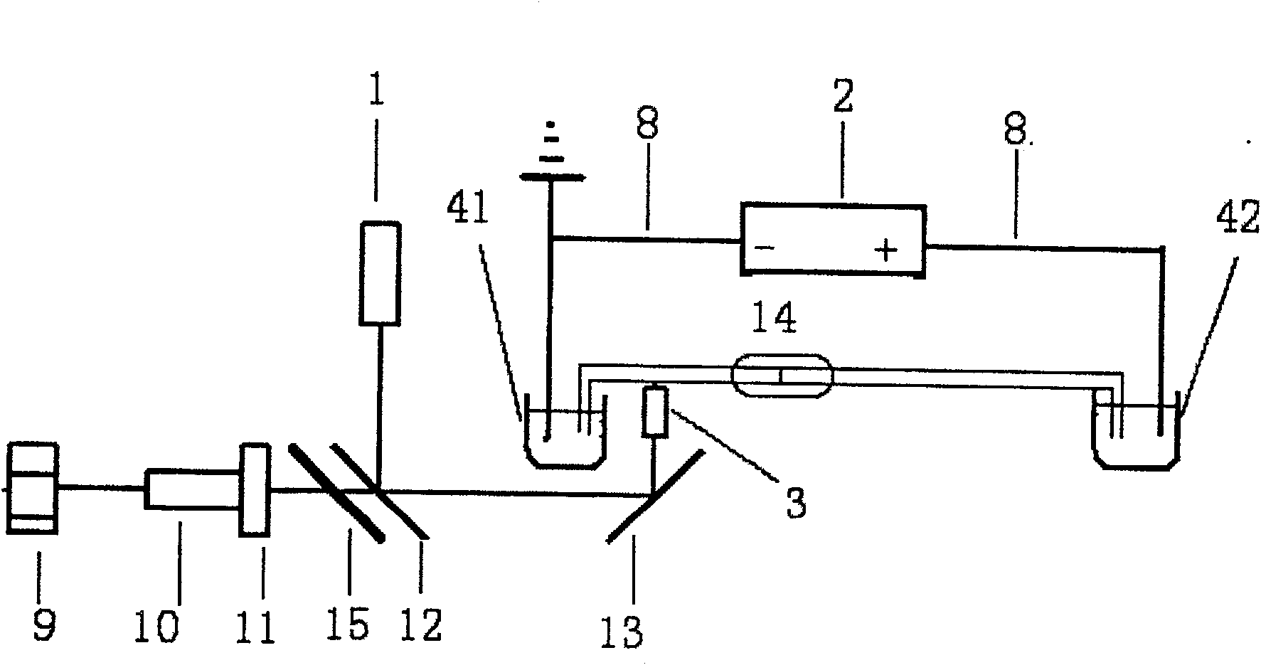
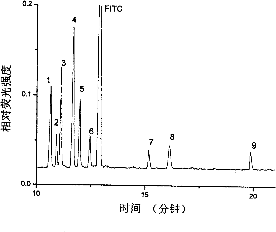
[0020] In order to experimentally demonstrate the feasibility and scientificity of the present invention, we experimentally selected a variety of anilines (9 types, see Table 1) to mix and derive, and use the multiphoton excitation fluorescence method to achieve the realization under three different separation and detection states. The separation and detection of aniline: adopt the traditional round capillary separation column for post-detection and square capillary separation column for detection; adopt the capillary electrophoresis-multiphoton excitation fluorescence column of the present invention for separation and detection.

[0021] The above-mentioned comparative experiment is as follows. The experiment proves that the separation effect of the round capillary is better than that of the square capillary, and its detection sensitivity is not better than that of the square capillary. The specific experiment is as follows:

[0022] 1. After the round capillary column, the elect...


PUM

PropertyMeasurementUnit
lengthaaaaaaaaaa

Abstract

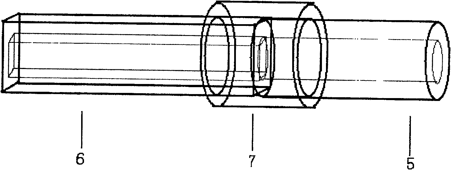
The invention discloses a detector on a capillary electrophoresis-multiphoton excitation fluorescent column, which includes a semiconductor laser, an objective lens, a computer, an acquisition card, a photomultiplier tube, a dichroic mirror, a band-pass filter, and a total reflection mirror , platinum electrode, DC high voltage power supply, first and second buffer pools and column detector. The on-column detector uses a Teflon tube to connect the square capillary and the circular capillary, wherein the circular capillary is used for separation (experiments have proved that the separation effect of the square capillary is not as good as the circular one), while the square capillary is used for on-column detection. The square capillary detected on the fluorescent column is combined with the circular capillary used for separation to realize on-column detection, which not only simplifies the traditional experimental equipment, reduces the cost of experimental equipment, simplifies the post-column detection method of complex operations, but also improves the detection sensitivity .

Description

Technical field [0001] The invention belongs to a high-sensitivity multiphoton fluorescence detection technology, and specifically relates to a capillary electrophoresis-multiphoton excitation fluorescence column detector. Background technique [0002] Capillary electrophoresis (high-performance capillary electrophoresis, HPCE), as a separation and analysis technology, has the advantages of high separation efficiency, short analysis time and small injection volume, and is simple to operate and easy to realize automation. With the diversification of separation modes and the innovation of detection technology, capillary electrophoresis has been widely used in the fields of life sciences, environmental health and medicine. [0003] Multi-photon Excited fluorescence (MPF) technology, as a new detection technology, has a small excitation volume (10 -18 L), low light damage and phototoxicity (using near-infrared laser), high sensitivity (zmol-ymol level detection limit) and low backgro...

Claims


Application Information

Patent Timeline
Patent Type & Authority Patents(China)
IPC IPC(8): G01N21/64G01N27/453B01D57/02
Inventor 刘笔锋骆清铭陈胜
Owner HUAZHONG UNIV OF SCI & TECH
Learn More