Supercharge Your Innovation With Domain-Expert AI Agents!

Contactor

A contactor and negative connection technology, applied in relays, electromagnetic relays, electrical components, etc., can solve the problems of AC contactor structure, power consumption and cost that are not well improved, and achieve simple structure, stable performance, and cost reduction. Effect

Inactive Publication Date: 2010-01-13
杨松鹤
View PDF5 Cites 0 Cited by
  • Summary
  • Abstract
  • Description
  • Claims
  • Application Information

AI Technical Summary

Problems solved by technology

However, due to the use of vulnerable and energy-consuming components such as electrolytic capacitors, silicon controlled rectifiers, and anti-magnetic coils in the realized circuit, the structure, power consumption, and cost of the AC contactor have not yet been improved.

Method used


Image

  • Contactor
  • Contactor
  • Contactor

Examples


Embodiment Construction

[0028] The present invention will be further described in detail below in conjunction with the accompanying drawings.

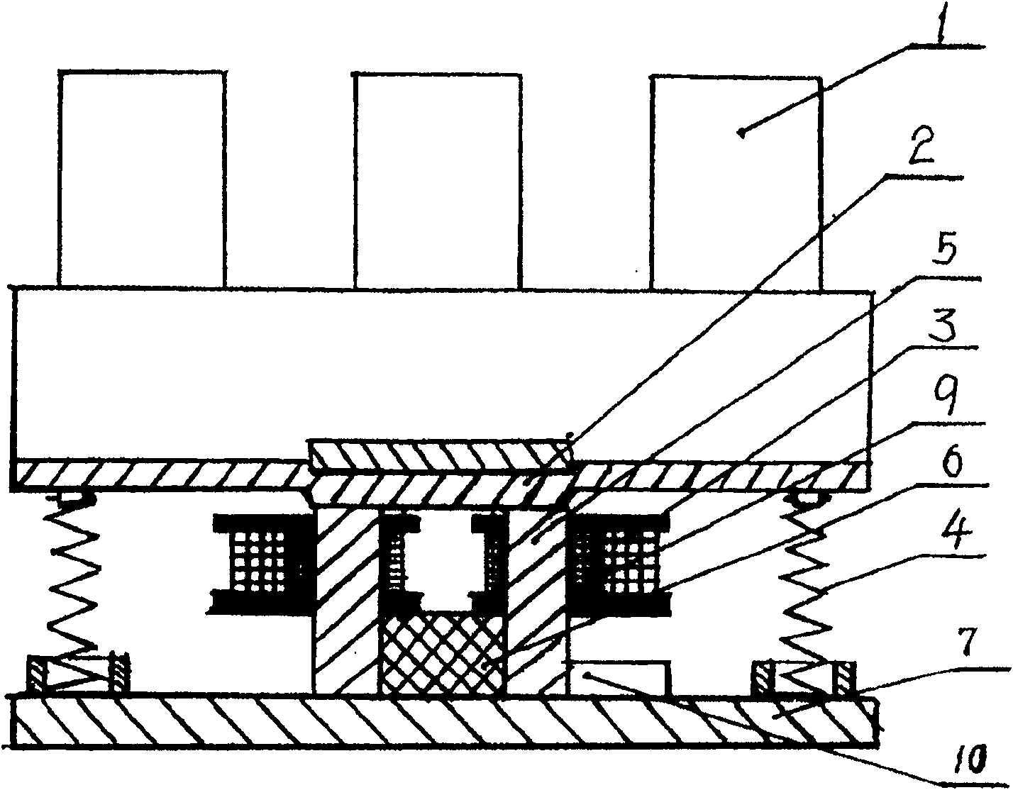
[0029] figure 1 It is a schematic diagram of the structure of the constant magnetic holding AC contactor in the prior art. In the figure, 1 is the main body, 2 is the upper moving iron core, 3 is the electromagnetic pull-in coil, 4 is the spring, 5 is the lower static iron core, and 6 is the permanent magnet. , 7 is the base, 9 is the anti-magnetic coil, and 10 is the capacitor releaser. This contactor uses four coils with reference numeral 3 and one coil with reference numeral 9, that is, 5 coils are used in total.

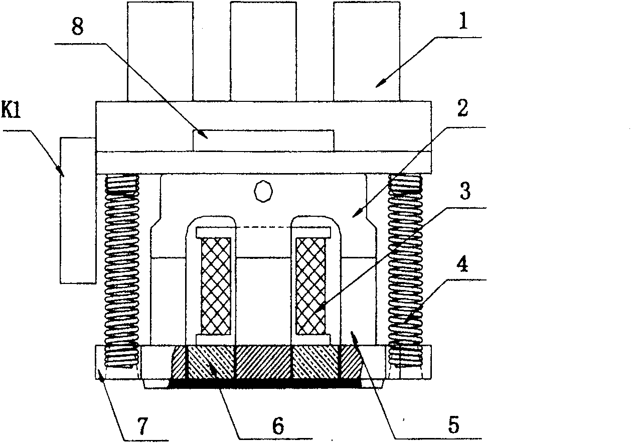
[0030] figure 2 It is a structural schematic diagram of the device of the present invention. The contactor of the present invention includes: a main body 1, an upper moving iron core 2, a lower static iron core 5 opposite to the upper moving iron core 2, and an intermediate iron core wound on the lower static iron core 5. The coil 3, the spr...


PUM


Abstract

A contactor includes a master, an upper dynamic iron core, a lower static iron core, a coil winded on the lower iron core, a spring and a constant magnet, also an electronic module for realizing magnet-keeping containing a commutating circuit, an amplifying circuit and an inverting circuit with three output ends. Since it applies an electronic module, it uses oil of the original contactor.

Description

technical field [0001] The invention relates to a switchgear for power supply, in particular to a contactor for a power automation system. Background technique [0002] Contactors have been widely used in power automation systems, cement plants, steel plants, chemical industry, light industry, mechanical power distribution and other industrial systems, involving all walks of life, with a consumption of about one billion in the country. [0003] At present, the contactors on the market generally have the disadvantages of high energy consumption, noise, easy to be burned by heat, easy to trip or even burn out load equipment due to grid voltage fluctuations. These disadvantages that exist have been improved very well, but the scope of promotion is limited due to imperfect technology, high cost, complex structure, and especially difficult access to automatic control circuits. [0004] For example, in the Chinese patent No. 200420025887.1, an integrated low-energy consumption no...

Claims


Application Information

Patent Timeline
Patent Type & Authority Patents(China)
IPC IPC(8): H01H47/32H01H47/02H01H49/00H01H51/00
Inventor 杨松鹤
Owner 杨松鹤
Features
  • R&D
  • Intellectual Property
  • Life Sciences
  • Materials
  • Tech Scout
  • Unparalleled Data Quality
  • Higher Quality Content
  • 60% Fewer Hallucinations
Learn More