Wide band high voltage intelligent resistance type voltage current combined sensor
A combined sensor, voltage and current technology, applied in the direction of voltage/current isolation, inductors, transformers, etc., can solve the problems of long signal transmission lines, interference, and affecting test accuracy, so as to achieve no secondary open circuit high voltage danger, low temperature drift, Strong anti-interference ability
- Summary
- Abstract
- Description
- Claims
- Application Information
AI Technical Summary
Problems solved by technology
Method used
Image
Examples
Embodiment 1
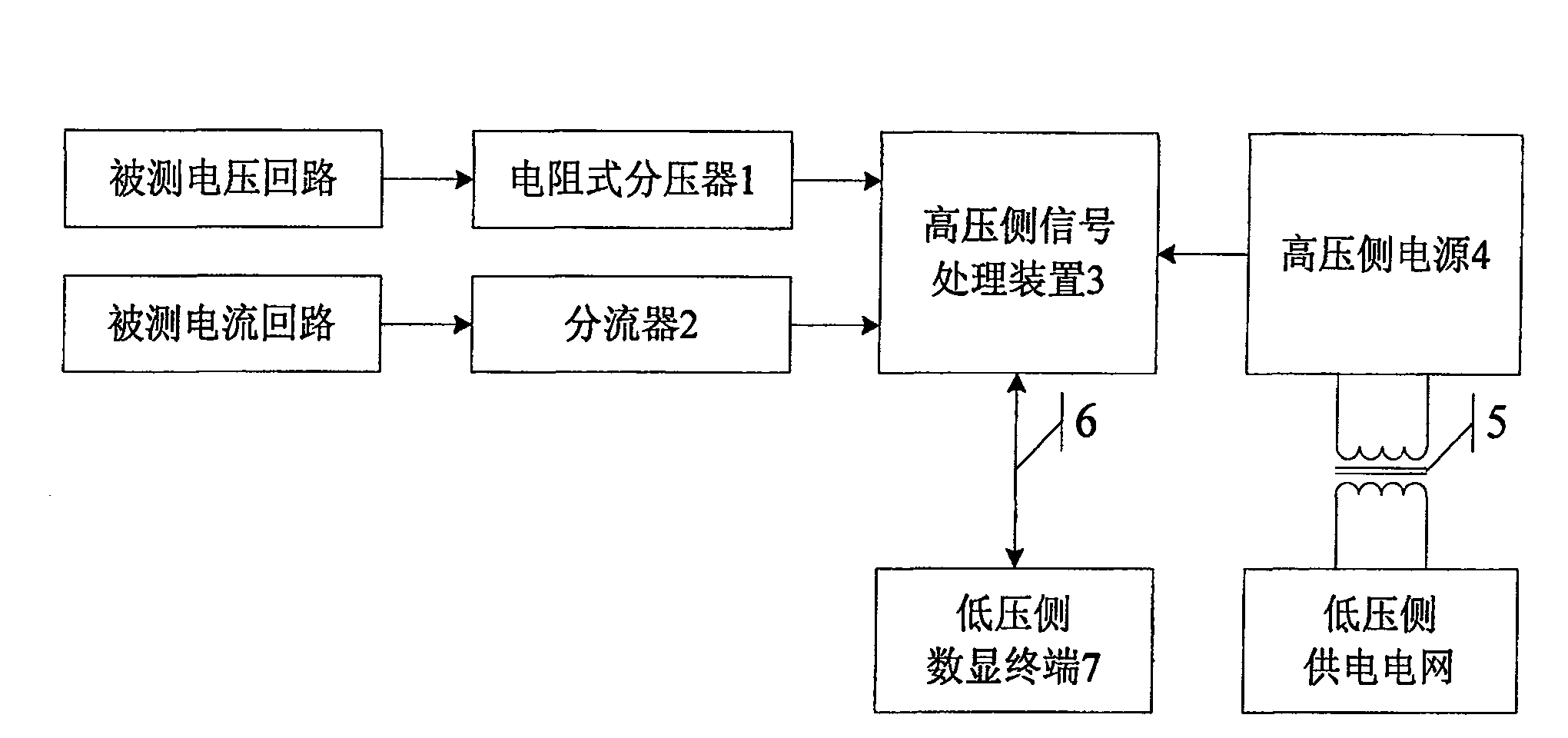
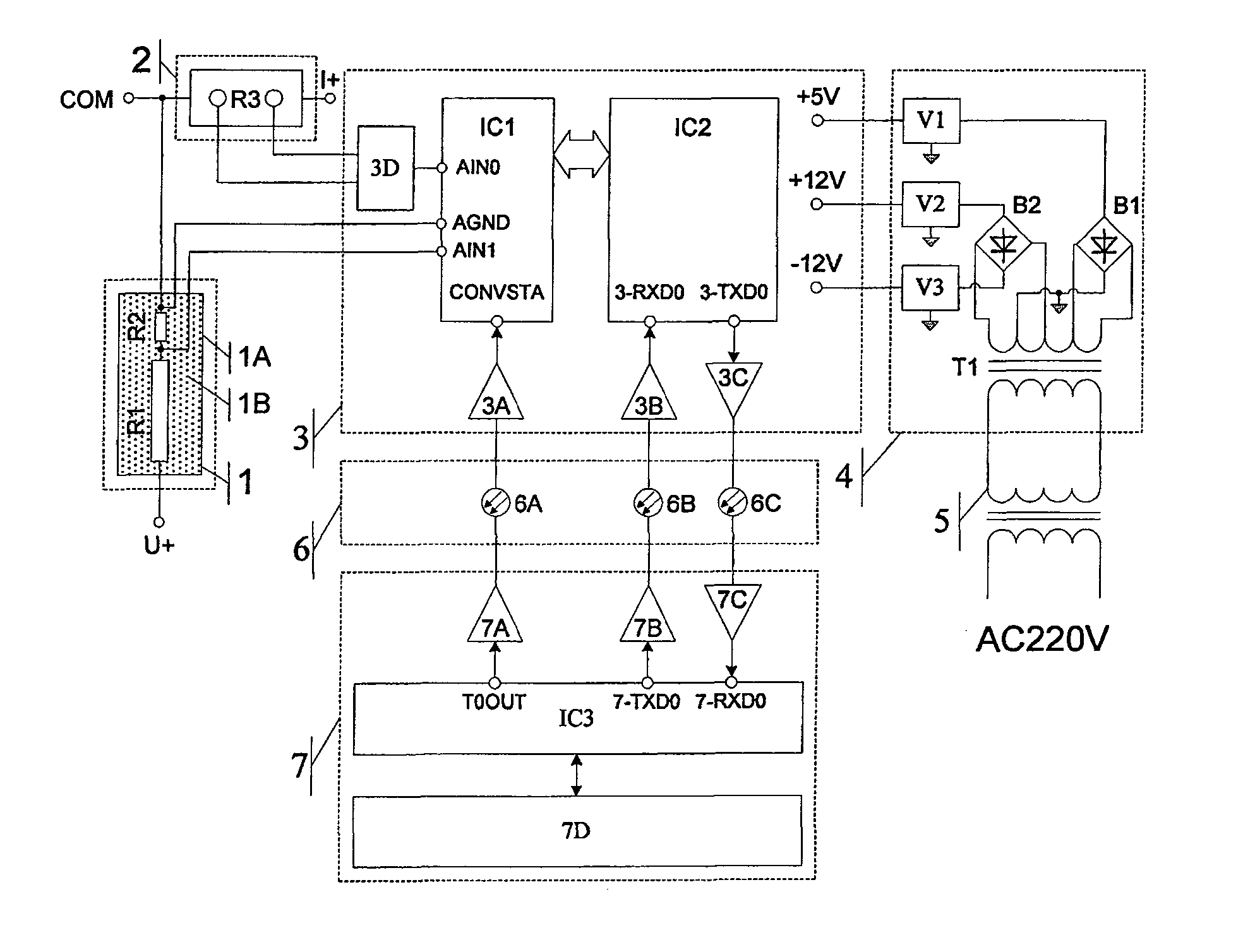
[0026] Embodiment 1: refer to figure 1 and figure 2 :
[0027] This embodiment includes a resistive voltage divider (1) for extracting voltage signals from the measured voltage loop, a shunt (2) for extracting millivolt-level voltage signals from the measured current loop, and a high-voltage side signal processing device (3) , a high-voltage side power supply (4), a high-voltage isolation transformer (5), a communication optical fiber group (6), and a low-voltage side digital display terminal (7).
[0028] In this embodiment, the low-voltage side power supply grid adopts AC220V mains power.
[0029] The analog voltage signal output by the resistive voltage divider (1) and the shunt (2) is connected to the high-voltage side signal processing device (3), and the high-voltage side signal processing device (3) connects the resistive voltage divider (1) and the shunt (2) The output analog voltage signal is converted into a digital signal and uploaded to the low-voltage side dig...
Embodiment 2
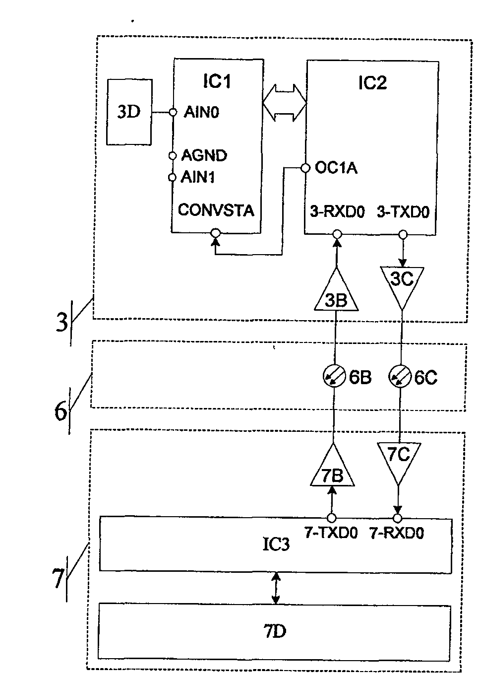
[0041] Refer to attached image 3 : (The figure omits the connection with figure 2 The same resistive voltage divider 1, shunt 2, high-voltage side power supply 4, and high-voltage isolation transformer 5) in this embodiment, the difference between this embodiment and embodiment 1 is that the broadband high-voltage intelligent resistive voltage-current combined sensor in this embodiment does not Concerned about the sampling time of the signal under test, that is, no synchronous sampling or phase comparison with other signals is required, so the high-voltage side signal processing device (3) omits the sampling clock receiver 3A, and the communication optical fiber group (6) omits the communication optical fiber 6A, The low-voltage side digital display terminal (7) saves the sampling clock transmitter 7A, and at the same time connects the A / D conversion start signal CONVSTA of the A / D converter IC1 directly to the clock output pin OC1A of the microprocessor IC2, and IC2 provide...
Embodiment 3
[0043] Refer to attached Figure 4 : (The figure omits the connection with figure 2 The same resistive voltage divider 1, shunt 2, high-voltage side power supply 4, high-voltage isolation transformer 5), the difference between this embodiment and embodiment 1 is that the broadband high-voltage intelligent resistive voltage-current combination sensor in this embodiment does not need Various instructions are set, so the high-voltage side signal processing device (3) can save the serial data receiver 3B, the communication fiber group (6) can save the communication fiber 6B, and the low-voltage side digital display terminal (7) can save the serial data receiver 3B. Data transmitter 7B.
PUM
 Abstract
Description
Claims
Application Information
 - R&D
- Intellectual Property
- Life Sciences
- Materials
- Tech Scout
- Unparalleled Data Quality
- Higher Quality Content
- 60% Fewer Hallucinations
Browse by: Latest US Patents, China's latest patents, Technical Efficacy Thesaurus, Application Domain, Technology Topic, Popular Technical Reports.
© 2025 PatSnap. All rights reserved.Legal|Privacy policy|Modern Slavery Act Transparency Statement|Sitemap|About US| Contact US: help@patsnap.com


