Ultra large power two-dimensional semiconductor lock phase array stable oscillation mode technique

A super-power, semiconductor technology, used in semiconductor lasers, semiconductor laser devices, laser components, etc., can solve problems such as oscillation and intensified external cavity deformation

Inactive Publication Date: 2010-02-03
蔡然
View PDF3 Cites 0 Cited by
  • Summary
  • Abstract
  • Description
  • Claims
  • Application Information

AI Technical Summary

Problems solved by technology

[0005] Using the working center wavelength as λ, the slow axis array period as d, and the cavity length as L C = d 2 / 2λ, the 1 / 4Talbot external cavity mirror technology whose normal direction of the external cavity mirror is perpendicular to the slow axis can successfully lock the phase of the high-power semiconductor array, but the corresponding far-field distribution is a double lobe structure, indicating that the corresponding oscillation mode is the highest order super mode; according to the distribution law of the fractional Talbot cavity field, in order to make the system oscillate in the fundamental supermode, to obtain an excellent output with a single lobe structure and close to the diffraction limit in the far field, the 1 / 4 Talbot external cavity mirror must be placed in the direction of the slow axis Appropriately deflecting at a certain angle, this is the way that the two-dimensional semiconductor stacked array adopts the external cavity technology to select the base supermode oscillation, and has successfully obtained engineering realization. However, when this technology is applied to the ultra-high-power two-dimensional semiconductor array lock At the same time, after tilting the outer cavity mirror with an adapted angle to make the array selection base supermode oscillate, although the cooling subsystem can ensure the continuous operation of the array, the residual thermal effect will still make the deformation of the outer cavity continue to aggravate, coupled with the vibration of the platform etc., resulting in the highest-order supermodel shock

Method used


Image

  • Ultra large power two-dimensional semiconductor lock phase array stable oscillation mode technique
  • Ultra large power two-dimensional semiconductor lock phase array stable oscillation mode technique
  • Ultra large power two-dimensional semiconductor lock phase array stable oscillation mode technique

Examples


Embodiment Construction

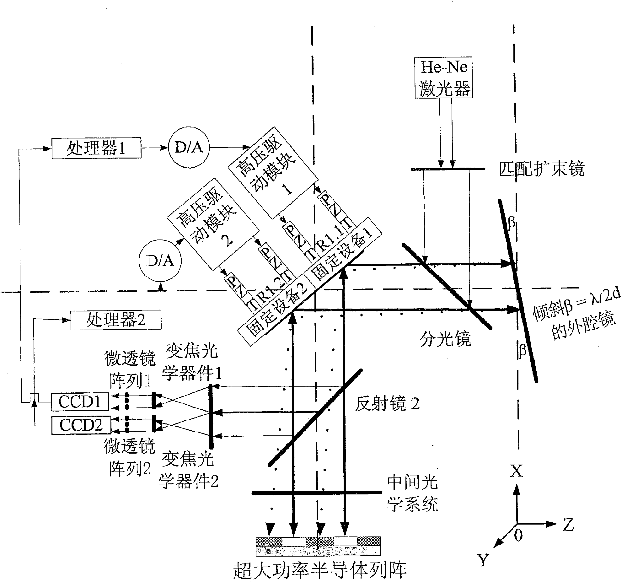
[0015] The He-Ne laser beam from the active sensing light source is expanded by the matching beam expander, reflected by the beam splitter, and projected to the 1 / 4Talbot external cavity mirror. After being reflected, it passes through the beam splitter and passes through the mirror R1.1 After being reflected by R1.2 and reflector 2, the He-Ne laser beam corresponding to R1.1 is imaged on CCD1 by zoom optical device 1 and microlens array 1, and the He-Ne laser beam corresponding to R1.2 is imaged by zoom optical device 2 , Microlens array 2 is imaged on CCD2, corresponding to the spot centroid of any sub-aperture (x C ,y C ),accessible

[0016] x C = Σ i , j M , N x ij ...


PUM


Abstract

This invention provides a double-path adaptive sensing compensated mode-stabilizing system technology, which puts forward a method for setting up two paths of parallel adaptive compensated mode-stabilizing systems with exchangeable positions including setting up a subsystem related to CCD1for testing change of an outer cavity and a subsystem related to CCD2 for compensating the change of the outercavity, in which, each path of the subsystems for testing the change test the He-Ne laser wavefront slope related parameters reflected by the outer cavity mirror and compute the shape-change volume of the outer cavity and necessary compensation volume, then the subsystems for compensation coordinated to each other compensate a directional change of the outer cavity, and a double-path mode-stabilizing system carries out cooperated optimized compensated operation on the basis of testing one direction of shape-change parameter by each path of adaptive sensing compensated mode-stabilizing systemto counteract the change of position of super-mode optical image aroused by beta-disturbance.

Description

technical field [0001] The invention belongs to the external cavity deformation measurement technology and compensation technology for stable ultra-high-power semiconductor phase-locked array oscillation mode, and relates to residual thermal effects caused by ultra-high-power semiconductor array selection base supermode vibration through the external cavity mirror deflection adaptation angle The method for automatic measurement and compensation of the deformation of the external cavity involves avoiding the vibration of the non-fundamental supermode caused by the deformation of the external cavity. Background technique [0002] The quantum efficiency of the semiconductor array is high, the output wavelength range covers 570nm to 1600nm, and the working life can reach millions of hours. The stacked array can provide ultra-high power laser output, and has a very broad and good performance in many fields such as industry and medicine. The application prospect, but because the l...

Claims


Application Information

Patent Timeline
Patent Type & Authority Patents(China)
IPC IPC(8): H01S5/40H01S5/00G02F1/35
Inventor 蔡然
Owner 蔡然
Why Eureka
Try Eureka