Industrial boiler using emulsifying coke mortar burning device

A technology for a combustion device and an industrial boiler, which is applied in the directions of using multiple fuel combustion, combination of multiple burners, and combustion air/fuel supply, etc., can solve the problems of energy waste, complicated combustion chamber structure and high manufacturing cost

Inactive Publication Date: 2010-03-17
广州迪森热能设备有限公司
View PDF9 Cites 0 Cited by
  • Summary
  • Abstract
  • Description
  • Claims
  • Application Information

AI Technical Summary

Problems solved by technology

It can be seen from the above analysis that, firstly, the backfired coal-water slurry liquid slagging combustion furnace is not suitable for the combustion of emulsified coke slurry; secondly, the combustion chamber temperature of the backfired coal water slurry liquid slagging combustion furnace is still low The ash melting point of the emulsified coke slurry ash cannot be reached, and the emulsified coke slurry ash cannot be liquefied; finally, the combustion chamber structure of the reverse combustion type coal-water slurry liquid slagging combustion furnace is complicated, and the manufacturing cost is high
[0007] In addition, in order to make the system operate continuously and normally, the slag receiving device at the lower part of the burner must be replaced in time, and the liquid slag also contains a large amount of waste heat that can be used. If the liquid slag is directly flowed into the slag receiving device, it will cause waste of energy
[0008] Finally, liquid slag removal cannot completely remove the soot, and a small amount of soot will enter the boiler cavity. If the soot is not cleaned in time, it may cause dangerous accidents if it accumulates over time. The soot on the surface of the furnace or water pipe is blown up and taken away in time

Method used


Image

  • Industrial boiler using emulsifying coke mortar burning device
  • Industrial boiler using emulsifying coke mortar burning device
  • Industrial boiler using emulsifying coke mortar burning device

Examples


Embodiment 1

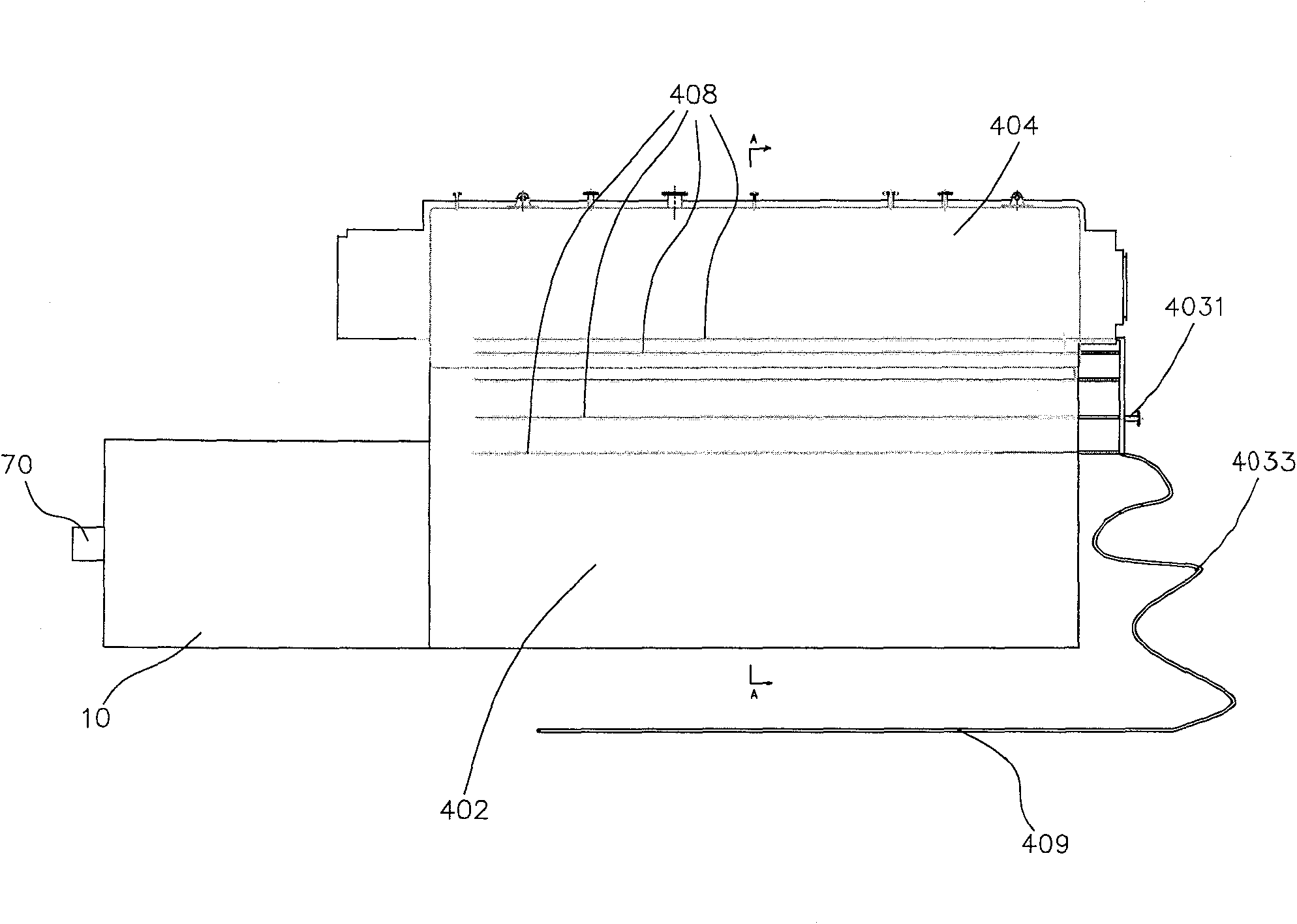
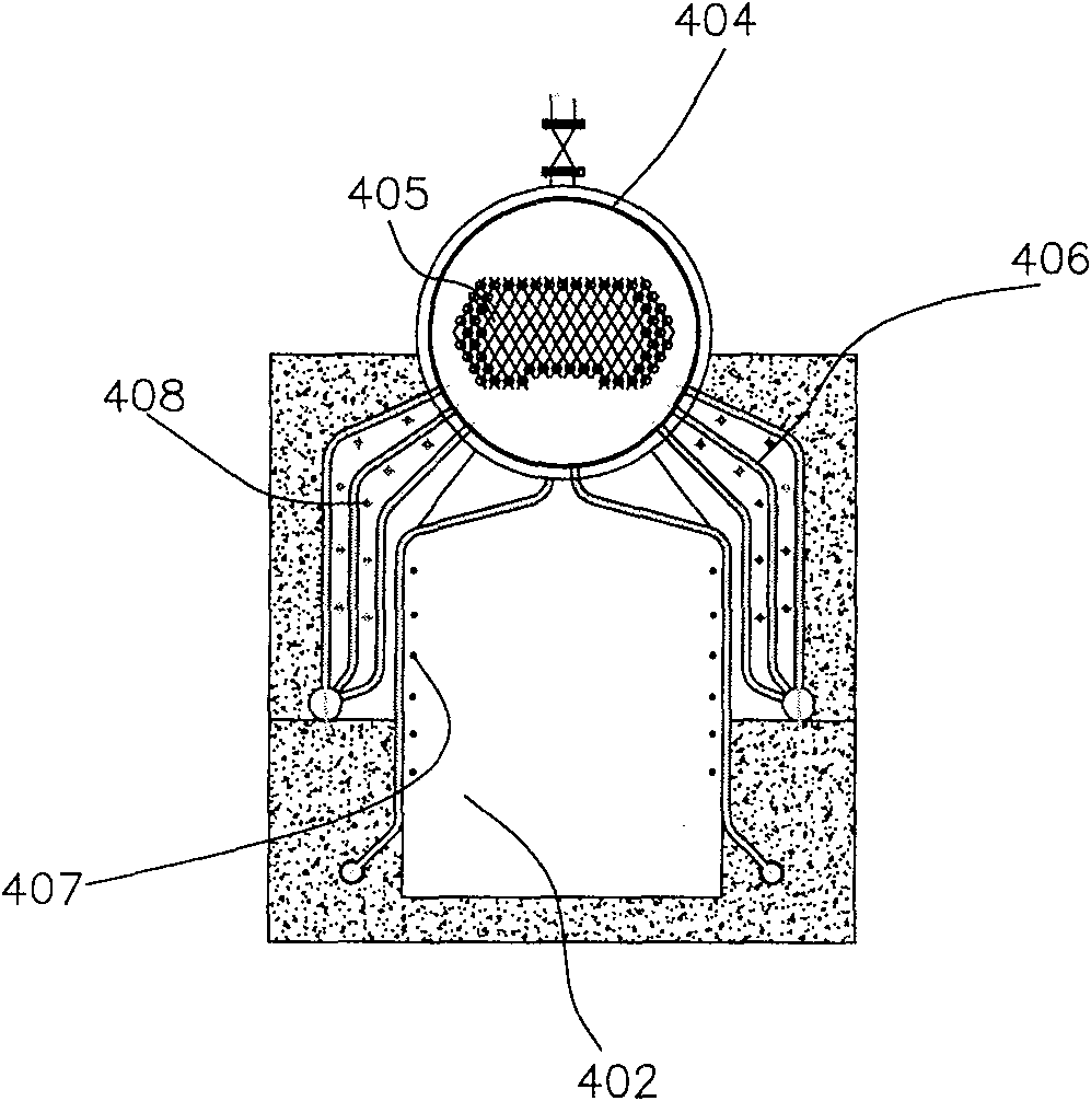
[0056] Please refer to figure 1 and figure 2 The industrial boiler of the present invention includes a horizontal boiler body and an emulsified coke slurry combustion device. Among them, the boiler body includes a furnace 402, a drum 404 arranged above the furnace 402, a water pipe 406 arranged in the upper middle of the furnace 402 and close to the side wall of the furnace, and a fire set in the central area of ​​the drum 404 and immersed in the water in the drum. Tube 405, ten convection zone soot blowing tubes 408 ( figure 1 Four of them are shown schematically in the middle) and six furnace soot blowing pipes 409 ( figure 1 One of them is shown schematically in ). The emulsified coke slurry combustion device includes a casing 10, an emulsified coke slurry burner 70, an oil burner (not shown), and a gas burner (not shown). The emulsified coke slurry combustion device is in communication with the furnace 402.

[0057] Wherein, the convection zone soot blowing pipe 408 and the...

Embodiment 2

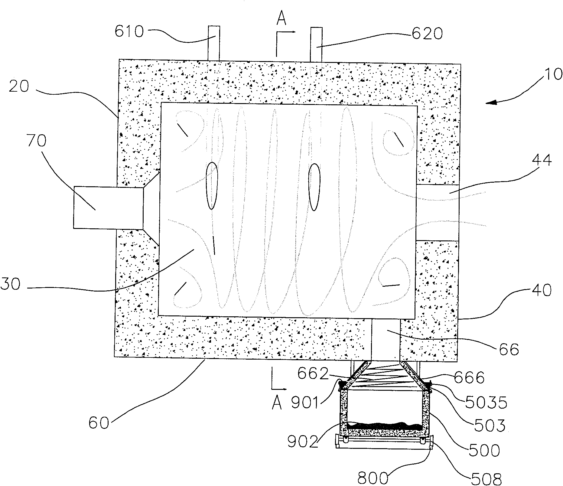
[0079] Please refer to Figure 5 and Image 6 , This embodiment is similar to embodiment 1, the difference lies in:

[0080] Two convection zone soot blowing pipes 408 are respectively used on both sides of the central area of ​​the furnace 402. The convection zone soot blowing pipe 408 is arranged adjacent to the water pipe 406. A part of the plural soot blowing holes on each convection zone soot blowing pipe 408 faces the water pipe 406. A part of the outer surface faces the inner surface of the furnace 402.

[0081] The opening area of ​​the liquid slag outlet 66 on the inner wall of the side wall 60 is approximately equal to one twentieth of the cross-sectional area of ​​the combustion space 30.

[0082] The vertical distance between the inner wall of the front end wall 20 and the inner wall of the rear end wall 40 is 1.5 times the inner diameter of the combustion space 30.

[0083] The diameter of the outlet 44 is approximately equal to one-half of the inner diameter of the combu...

Embodiment 3

[0092] This embodiment is similar to Embodiment 1, except that:

[0093] Three soot blowing pipe inlets 407 are provided on one end wall of the furnace 402 away from the emulsified coke slurry combustion device. The boiler body includes three furnace soot blowing pipes 409 that can be inserted and exited from the soot blowing pipe inlet 407 and whose length is slightly longer than the length of the furnace 402.

[0094] The industrial boiler using the emulsified coke slurry combustion device is provided with two spaced apart liquid slag outlets 66 of the same size. The opening area of ​​each liquid slag outlet 66 on the inner wall of the side wall 60 is approximately equal to three times the cross-sectional area of ​​the combustion space. one tenth.

[0095] The two liquid slag outlets 66 are surrounded by the same transition cavity 666 and communicate with the slag containing space 505 of the same slag discharge truck 500.

[0096] The vertical distance between the inner wall of the ...


PUM


Abstract

The present invention discloses an industrial boiler adopting emulsified coke slurry combustion equipment. It includes boiler self-body and emulsified coke slurry combustion equipment. The boiler self-body includes furnace cavity, boiler barrel set over the furnace cavity, water pipe which is set in the upper portion of said furnace cavity and is adjacent to the side wall of furnace cavity and fire pipe which is set in the central zone of boiler barrel and is soaked in the water of boiler barrel interior. Said emulsified coke slurry combustion equipment includes a shell body formed from frontend wall, rear end wall and side wall, in said shell body interior a cylindrical combustion space is formed, on the front end wall are set at least one emulsified coke slurry combustor, at least one oil combustor and / or at least one gas combustor and on the rear end wall an outlet is cut, said outlet is communicated with the furnace cavity. Said invention also provides the working principle of said industrial boiler and its concrete operation method.

Description

Technical field [0001] The invention relates to an industrial boiler, in particular to an industrial boiler using an emulsified coke slurry combustion device. Background technique [0002] The cleaner energy sources currently used in industrial boilers are mainly oil, natural gas or gas, etc. However, this has greatly increased the fuel cost of industrial boilers, and has seriously affected the survival of enterprises that use and manufacture industrial boilers. [0003] For this reason, those skilled in the art are working hard to develop new usable energy sources. Emulsified coke slurry fuel with low price, high efficiency and clean has gradually become the new favorite in this field. The use of emulsified coke slurry fuel in industrial boilers can not only rationally utilize natural resources, but also reduce the fuel cost of industrial boilers. Therefore, countries all over the world are vigorously promoting emulsified coke slurry combustion technology. [0004] However, when e...

Claims


Application Information

Patent Timeline
Patent Type & Authority Patents(China)
IPC IPC(8): F23J3/00F23J1/08F23D17/00F23D23/00F23C1/00F23C5/00F23C7/00F23L1/00F24H1/00F22B11/00
Inventor 常厚春李祖芹马革耿生斌陈永超刘效洲
Owner 广州迪森热能设备有限公司
Why Eureka
Try Eureka