Method for raising intensity of long periodic optical-fibre grating and reducing tape width and optical-fibre grating

A fiber grating and long-period technology, which is applied in cladding optical fiber, optical waveguide light guide, optical waveguide coupling, etc., can solve the problems of LPFG intensity and bandwidth indicators that cannot be achieved, and achieve easy batching, high grating strength, and simple structure Effect

Inactive Publication Date: 2007-07-18
CHONGQING UNIV
View PDF0 Cites 8 Cited by
  • Summary
  • Abstract
  • Description
  • Claims
  • Application Information

AI Technical Summary

Problems solved by technology

This has directly led to the fact that the strength and bandwidt

Method used


Image

  • Method for raising intensity of long periodic optical-fibre grating and reducing tape width and optical-fibre grating
  • Method for raising intensity of long periodic optical-fibre grating and reducing tape width and optical-fibre grating
  • Method for raising intensity of long periodic optical-fibre grating and reducing tape width and optical-fibre grating

Examples


Embodiment Construction

[0044] The present invention will be further elaborated below in conjunction with accompanying drawing:

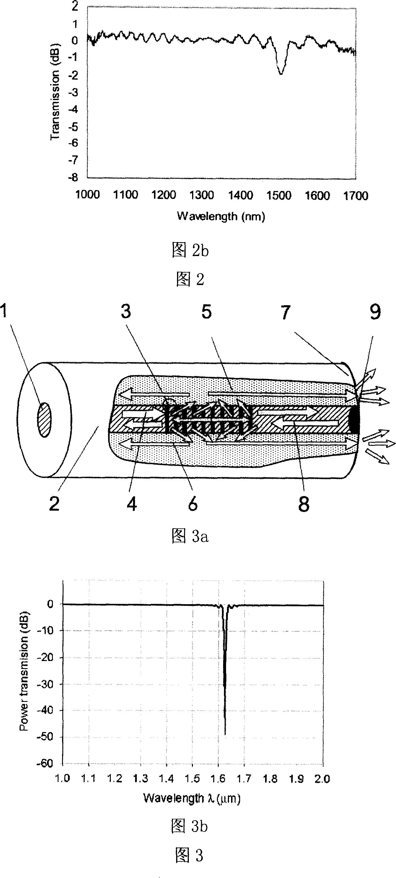
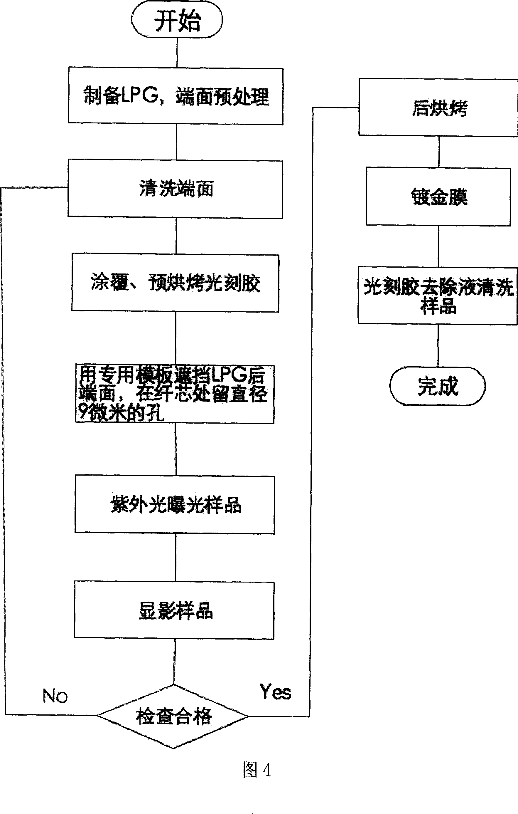
[0045] Referring to Fig. 3a, a long period fiber grating is composed of a core 1, a cladding 2, a grating region 3, a grating rear end face 7, a core mode reflector 9 and the like. The core mode reflector 9 is a gold-plated reflective surface, which is made at the end of the fiber core on the rear end face 7 of the grating, and has a diameter of 9 microns, which is the same as the diameter of the fiber core 1 . The production adopts micro-electromechanical system (MEMS) and micro-nano manufacturing technology, see Figure 4, the process flow is as follows:

[0046] 1) Preprocessing:

[0047] Prepare a well-made LPFG, and process its rear end surface into a mirror surface;

[0048] 2) Cleaning:

[0049] Soak in sulfuric acid solution for 10 minutes, rinse with distilled water, and dry with nitrogen; put in acetone solution, ultrasonically clean for 3 minutes, rinse with d...


PUM


Abstract

A method for increasing LPFG intensity and decreasing bandwidth includes setting a core mode reflector at back end of LPFG, only reflecting fiber core fundamental mode but not reflecting the cladding mode by said reflector, reflecting fiber core fundamental mode light passed grating region back to let it pass the same grating region twice and to let light satisfied with phase matching condition be coupled to cladding layer twice for realizing purpose of increasing couple intensity by square means and making grating length be doubled i.e. decreasing bandwidth.

Description

technical field [0001] The invention belongs to the field of optical fiber passive devices and the technical field of micro-electromechanical systems (MEMS), and specifically relates to the long-period optical fiber grating technology. Background technique [0002] In ordinary optical fiber, light exists and transmits in the form of a certain mode; usually these modes are relatively independent and do not exchange energy with each other; but when disturbed by the outside, the transmission conditions in the optical fiber change, and the mode transmitted in it Also be affected, some modes will exchange energy between them, this phenomenon is called mode coupling. Generally, the random mode coupling caused by random disturbance is harmful to the signal transmission in the fiber and needs to be avoided; however, if some regular disturbances are artificially designed, the energy exchange between the modes can be purposely controlled to realize the control of the mode in the fiber...

Claims


Application Information

Patent Timeline
IPC IPC(8): G02B6/34G02B6/02G02B6/26G02B1/10
Inventor 朱永陈伟民符欲梅
Owner CHONGQING UNIV
Why Eureka
Try Eureka