Gas insulation switch device

A gas-insulated switch and insulating sleeve technology, which is applied in switchgear, switchgear setting, panel/switch station circuit device, etc., can solve the problems of increased manufacturing cost, unsightly appearance, increased connection surface, etc., and achieves zero reduction. The number of parts, convenient inspection and maintenance, high stability and performance

Inactive Publication Date: 2007-07-18
CHINA XD ELECTRIC CO LTD
View PDF0 Cites 12 Cited by
  • Summary
  • Abstract
  • Description
  • Claims
  • Application Information

AI Technical Summary

Problems solved by technology

[0003] In the above-mentioned gas insulated switchgear, the circuit breaker is arranged vertically, and the two outlets of the circuit breaker are not at the same height, which leads to the elevation of the position of the isolating switch, the quick earthing switch and the metal container on the left side of the circuit breaker, which leads to two The height of the side components is inconsistent, the appearance is not beautiful, especially the inspection and maintenance are inconvenient
Due to the vertical arrangement of the casing, in order to ensure the minimum insulation distance requirements between the overhead transmission line and the nearest busbar and between two busbars, the total length is unnecessarily increased, resulting in an increase in the number of parts and the amount of insulating gas. , needs to be disassembled and transported, and the on-site installation and construction of the substation has a large workload and a long cycle, and the cost is high
[0004] In the above-mentioned conventional gas insulated switchgear, since the circuit breaker and two current transformers are arranged in three containers, the types and numbers of containers increase, the connection surfaces increase, and the manufacturing cost increases.
In addition, since the grounding switch and the isolating switch are relatively independent, and are driven by different operating mechanisms and interlocked electrically, there are many parts, complex machinery, and large size and volume of the entire device, resulting in lower manufacturing costs. increased

Method used


Image

  • Gas insulation switch device
  • Gas insulation switch device
  • Gas insulation switch device

Examples


Embodiment 1

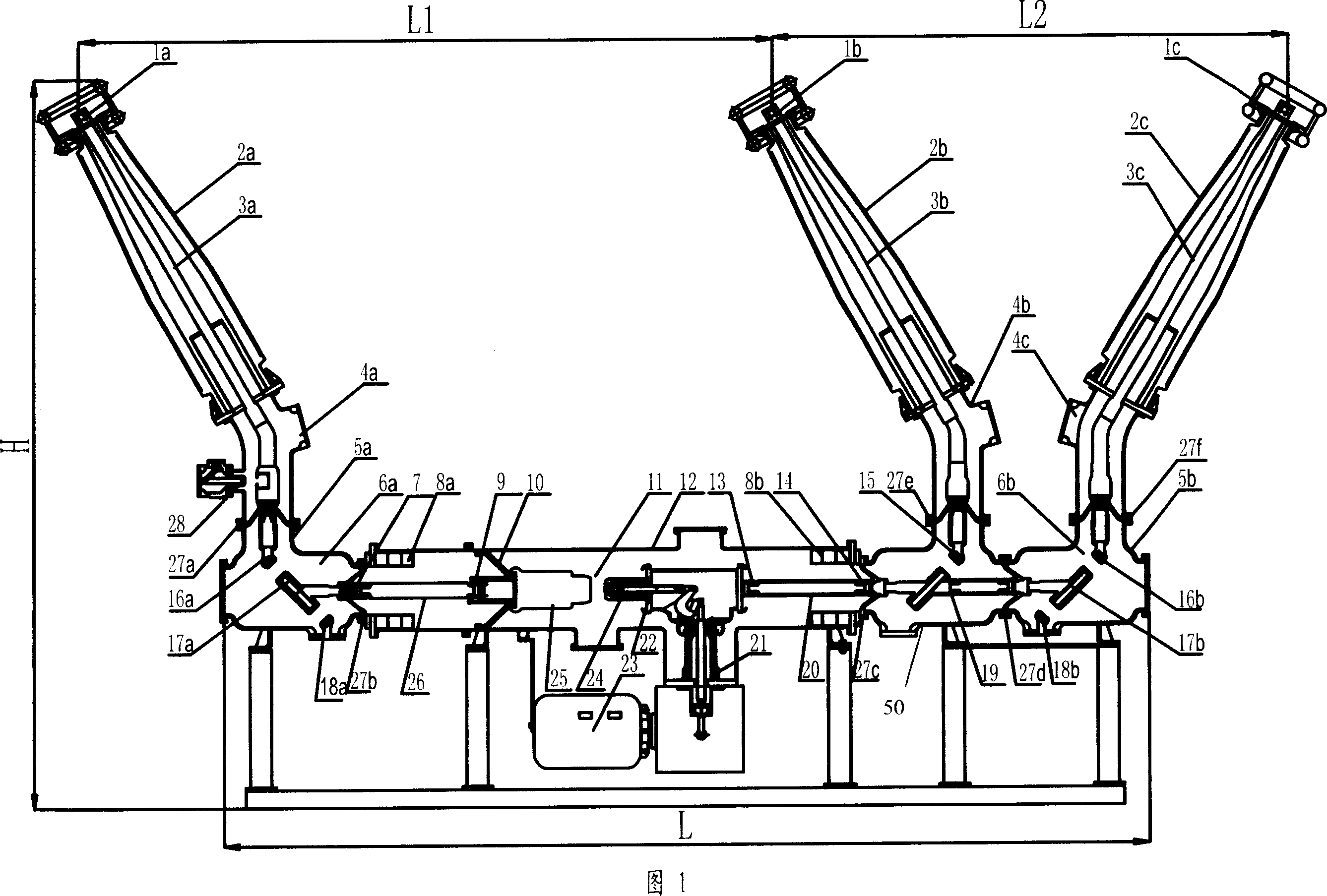
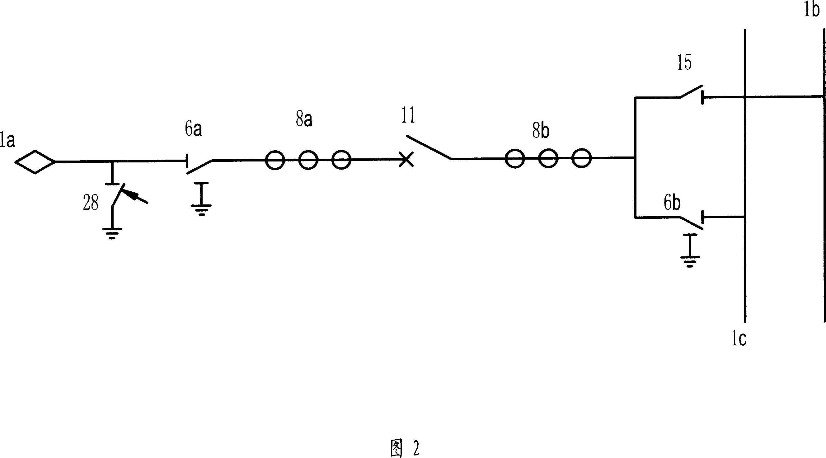
[0032] FIG. 1 shows a cross-sectional structure of a gas insulated switchgear (HGIS) according to a first embodiment of the present invention. Figure 2 is a schematic circuit diagram of the HGIS. This embodiment is applied to a double-bus power station in a power system.

[0033] In this embodiment, the circuit breaker 11 and the current transformers 8a, 8b are arranged horizontally in an axially extended housing 12, and the isolation grounding switch 6a and the isolation grounding switch 6b connected to the isolation switch 15 are placed on the left and right sides of the circuit breaker 11 respectively. The isolated ground switch containers 5a and 5b.

[0034] The housing 12 is made of aluminum material into a horizontal cylinder with a horizontal axis. Insulating pots 27b, 27c are installed at the two ends of the housing; they are respectively connected to the left side of the isolating and grounding switch container 5a and the isolating switch container 50, and the right...

Embodiment 2

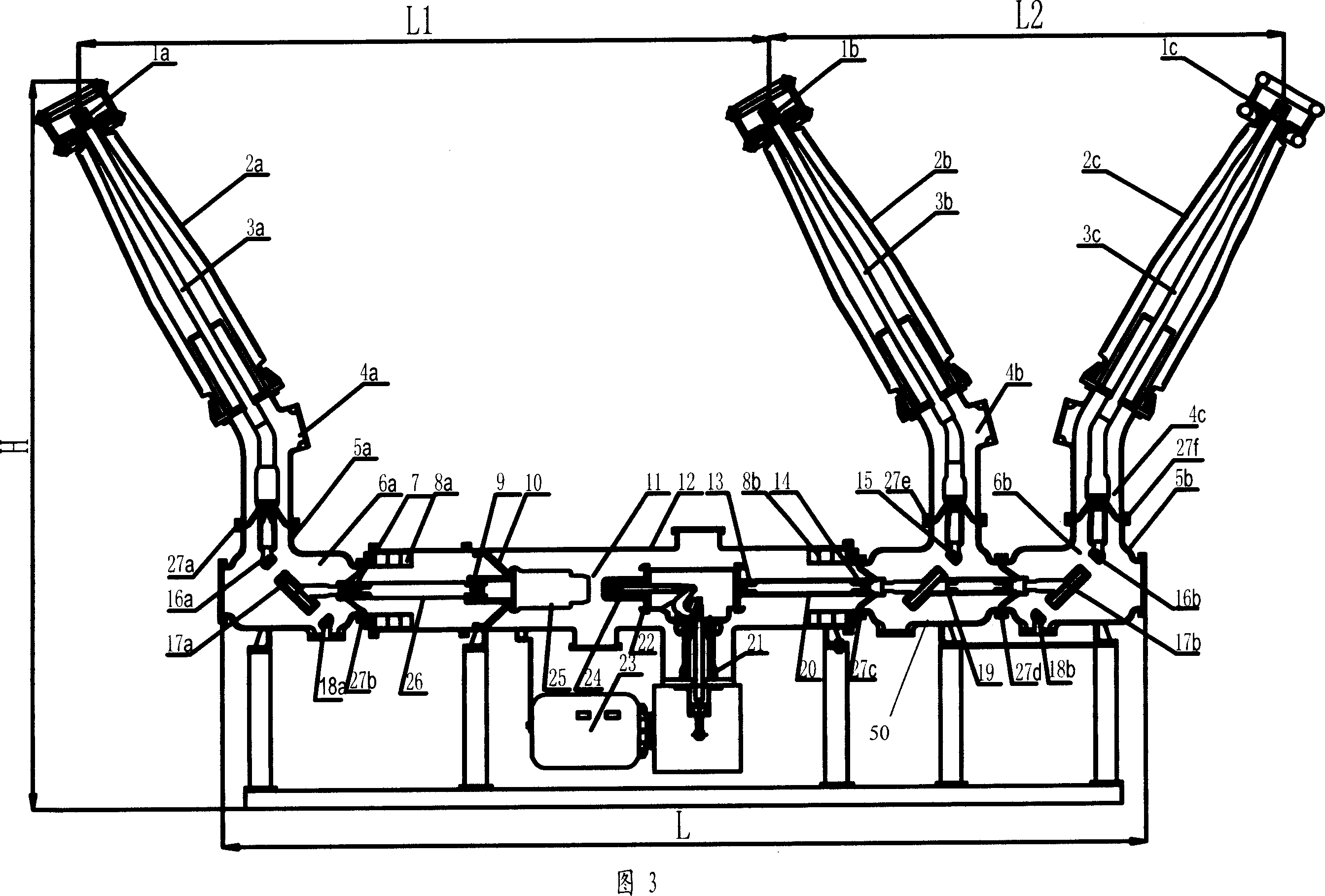
[0041] Fig. 3 is a cross-sectional view of an HGIS according to a second embodiment of the present invention.

[0042] According to the needs of the power system, sometimes the fast grounding switch 28 in FIG. 1 does not need to be installed on the incoming line side. In this embodiment, except that the fast grounding switch 28 is not provided, other configurations and structures are the same as those in Embodiment 1.

Embodiment 3

[0044] 4 and 5 are a sectional view and a circuit diagram of an HGIS according to a third embodiment of the present invention.

[0045] This embodiment is applied to a power station with single bus connection in the power system. The HGIS of this embodiment forms a conductive path through the power system overhead line 1a, the isolation grounding switch 6a, the current transformer 8a, the circuit breaker 11, the current transformer 8b, the isolation grounding switch 6b, and the bus bar 1b. Its structure is different from the first embodiment in that the isolating switch 15, the isolating switch container 50 and the metal airtight container 4b are omitted; the right side of the housing 12 is directly connected to the container 5b through the insulating basin 27c, and the connecting terminal 14 of the current transformer 8b is connected to the container 5b. The moving contact 17b of the isolating earthing switch 6b is directly connected, and the rest of the structure is the same...


PUM


Abstract

The invention discloses a gas insulated switchgear, including at least two isolation units and two earth units, breaker units connect with the isolation units and the earth units, and a shell contains insulating air and the breaker units, and the axis of the shell is in horizontal direction. The described two isolation units and the earth units are set on both sides of the breaker unit, which are the composite isolation-earth switch base on isolation function and earth function, and it achieves a mechanical interlock about the isolation function and earth function. The two isolation-earth switches are placed on each side of the two isolation-earth switch containers, and the top of each container vertically connects a metal airtight container and an insulation sleeve, and the insulation sleeve is set vertically. The isolation-earth switch connects to a conductor overhead through the insulation sleeve on the left and connects to a bus conductor of electricity overhead through the insulation sleeve on the right.

Description

technical field [0001] The invention relates to a switchgear for power transmission and distribution, in particular to a gas insulated switchgear (HGIS) which is placed outdoors and connects overhead power transmission lines and non-enclosed air-insulated busbars. Background technique [0002] The traditional gas insulated switchgear (see Figure 7) is arranged vertically with three bushings, the circuit breaker is arranged vertically, and the two current transformers are arranged separately from the circuit breaker. Three groups of disconnectors have two groups vertically arranged, one group Arranged horizontally, the grounding switch and isolating switch are independent components, which are operated by different mechanisms to realize the interlocking requirements of the isolating switch and grounding switch in the power system by electrical means. [0003] In the above-mentioned gas insulated switchgear, the circuit breaker is arranged vertically, and the two outlets of th...

Claims


Application Information

Patent Timeline
Patent Type & Authority Applications(China)
IPC IPC(8): H02B13/035H02B13/045H02B13/065H02B1/24H01H33/34H01H33/40
Inventor 申春红马增锐南振乐王瑞丽南方史方颖
Owner CHINA XD ELECTRIC CO LTD
Why Eureka
Try Eureka