Method and equipment for producing steel-plastics composite tube with two layers of polymer layer

A technology of steel-plastic composite pipe and polymer layer, which is applied in the direction of tubular objects, other household utensils, household utensils, etc., can solve the problem that the interface is not easy to be firmly bonded and compounded, and achieve high bearing pressure, strong corrosion resistance, and pressure bearing The effect of high ability

Inactive Publication Date: 2007-07-25
甘国工
View PDF5 Cites 20 Cited by
  • Summary
  • Abstract
  • Description
  • Claims
  • Application Information

AI Technical Summary

Problems solved by technology

[0005] The production method of the steel-plastic composite pipe with two polymer layers of the present invention comprises bending the steel plate or steel strip with holes longitudinally or spirally winding and welding it into a cylindrical metal skeleton, or winding warp steel wires with latitudinal steel wires The cylindrical frame is welded, and at least two extruders are used, and the molten polymer extruded by one of the extruders passes through the flow channel of the extrusion die, the molding cavity and the core mold to pass through the cylindrical metal frame with holes , the skeleton is covered to form the pipe wall, and the molten polymer extruded by another extruder will pass through the flow channel of the extrusion die, the molding cavity and the core film without passing through the cylindrical metal skeleton. The inner layer or outer layer of the formed pipe wall is compounded with a polymer layer, and the pipe is cooled and shaped to produce a steel-plastic composite pipe with a two-layer polymer layer with a cylindrical reinforced metal skeleton, using at least two The extruder can produce a steel-plastic composite pipe with two types of performance plastic layer pipe wall, one of which extrudes a polymer with a polar group (such as a graft-modified polymer with a carboxyl or hydroxyl group) Or carbonyl polar group or polar polyethylene or polypropylene or silane crosslinking (or crosslinkable) polymer with polar group) through the flow channel of the extrusion die and the molding cavity and core mold Then pass through the cylindrical metal skeleton with holes, and wrap the skeleton to form the pipe wall, which solves the technical problem that the interface between the metal and polyethylene is not easy to be firmly bonded and combined into one. Another extruder subsequently extrudes the melt polymerization Without passing through the cylindrical metal skeleton, a polymer layer is compounded on the inner or outer layer of the formed pipe wall. This layer of polymer can be ordinary polyethylene (HDPE) or polypropylene (PP) ) or non-crosslinked heat-resistant polyethylene (PE-RT)

Method used


Image

  • Method and equipment for producing steel-plastics composite tube with two layers of polymer layer
  • Method and equipment for producing steel-plastics composite tube with two layers of polymer layer
  • Method and equipment for producing steel-plastics composite tube with two layers of polymer layer

Examples


Embodiment 1

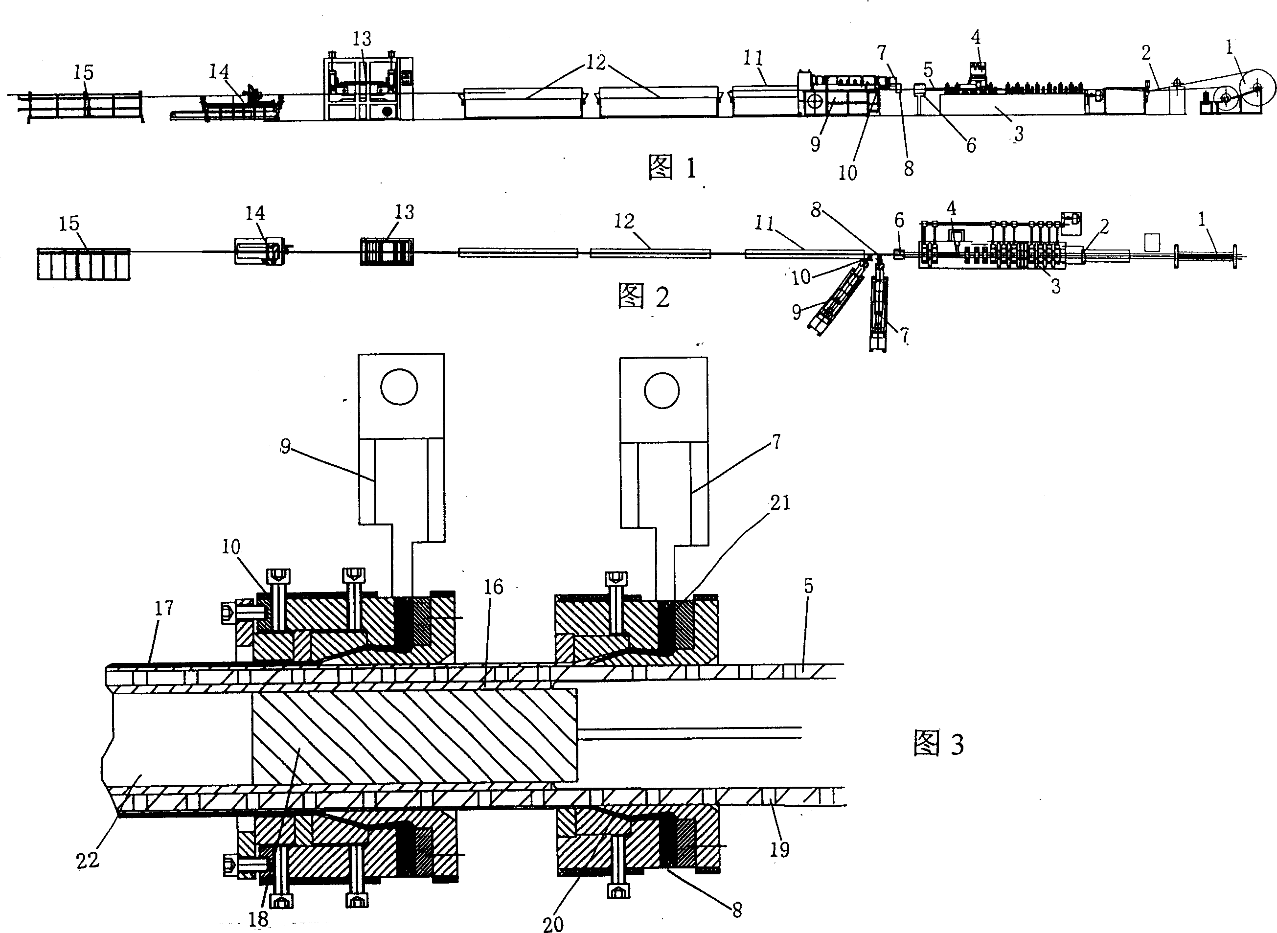
[0026] Fig. 1-Fig. 3, have provided the apparatus diagram of embodiment 1 of the present invention. Referring to Fig. 1 and Fig. 2, an unwinding machine 1 with perforated steel strip 2, a cylindrical perforated steel skeleton forming mechanism 3, a cylindrical perforated steel skeleton welding mechanism 4, and a welded forming are arranged in sequence according to the composite pipe forming process The tubular perforated steel frame 5, the heater 6 of the cylindrical perforated steel frame 5, the extruder 7 covering the polymer layer of the perforated steel frame, the extrusion die head of the polymer layer coated with the perforated steel frame 8. Outer layer extruder 9, outer layer extrusion die head 10, composite pipe cooling calibrating box 11, composite pipe spray cooling water tank 12, composite pipe tractor 13, cutting machine 14, pipe stacking rack 15.

[0027] Referring to Fig. 1, Fig. 2 and Fig. 3, the perforated steel strip 2 with the opening 19 is welded by the wel...

Embodiment 2

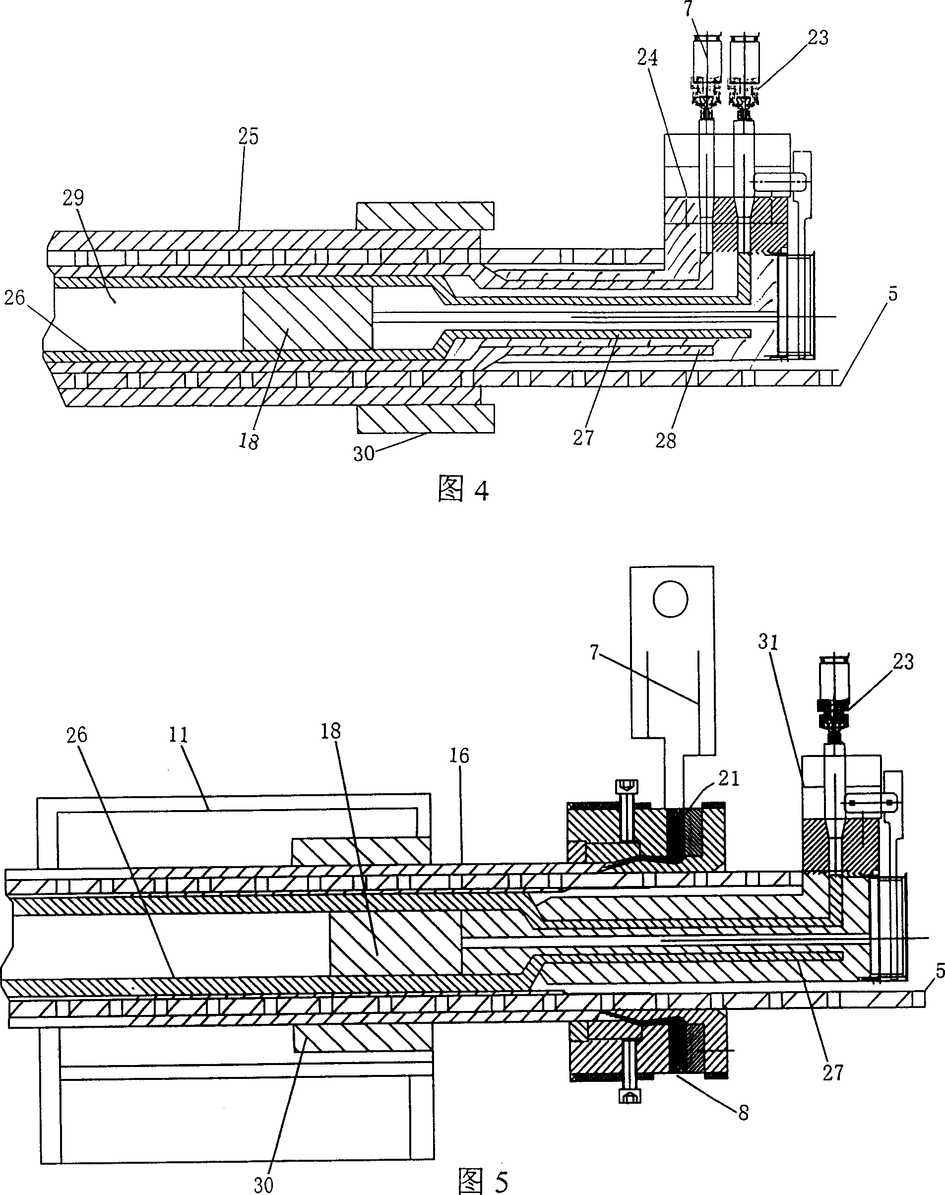
[0029] Figure 4 shows the layout of the extrusion die in the device of Example 2 of the present invention. Embodiment 2 is basically the same as Embodiment 1. The difference is that the inner layer runner 27 and the skeleton cladding layer runner 28 of the co-extrusion die head 24 that extrudes the cladding layer 25 of the composite skeleton 5 and the inner layer tube 26 extend into the inner cavity of the cylindrical metal skeleton. Yes, the polymer with polar groups extruded by the extrusion die arranged in the inner cavity of the cylindrical metal skeleton and its flow channel passes through the holes of the cylindrical metal skeleton to coat the skeleton to form the tube wall 25 (that is, the skeleton 5 cladding layer), the polymer continuum extruded by the extrusion die arranged in the inner cavity of the cylindrical metal skeleton and its flow channel does not pass through the cylindrical metal skeleton, under the joint action of the outer molding cavity 30 The polyethy...

Embodiment 3

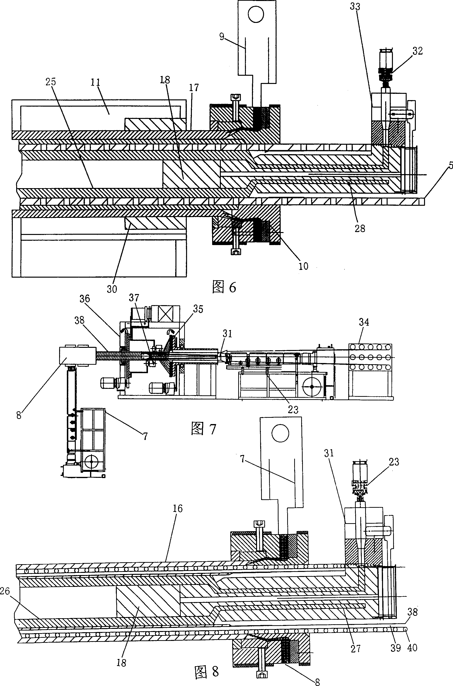
[0031] Figure 5 shows the layout of the extrusion die in the device of Example 3 of the present invention. Embodiment 3 is basically the same as Embodiment 1. The difference is that the polymer 21 with polar groups extruded by the extruder 7 covering the perforated steel skeleton polymer layer passes through the flow channel and molding cavity of the extrusion die 8 to pass the polymer 21 through the cylindrical metal The hole 19 of the skeleton covers the skeleton to form the pipe wall 16 (i.e. the cladding layer of the skeleton 5), and the polymer continuum extruded by the inner layer extruder 23 passes through the inner layer extrusion die 31 on the formed pipe wall On the inner layer of 16, compound one deck polymer 26 again. In Embodiment 3, the outer molding cavity 30 is installed in the cooling calibrating box 11 .


PUM


Abstract

A method for preparing the composite steel-plastics pipe with two polymer layers includes such steps as providing steel plate or steel band with holes, longitudinal curving or spiral rolling, welding to become a cylindrical metal skeleton, using an extruder to extrude out the fused polymer and make it to pass through the holes for wrapping the metal skeleton to form pipe wall, using another extruder to extrude out the fused polymer but make it not to pass through holes to form a polymer layer on formed pipe wall, and cooling. Its apparatus is also disclosed.

Description

Technical field: [0001] The invention relates to a production method of a steel-plastic composite pipe, in particular to a method in which the molten polymer extruded by an extruder passes through a cylindrical metal skeleton with holes to form a cladding pipe wall of the metal skeleton, and then extruded and compounded. A production method and device for forming the outer layer (or inner layer) of a steel-plastic composite pipe. Background technique: [0002] There are currently three methods and devices for the production technology of using a metal skeleton with holes as a reinforcement, extruding a composite polymer material on the skeleton as a continuum to wrap the skeleton to form a steel-plastic composite pipe: the first Such as British Patent GB2255, 148A92.10.28, Chinese Patent Application No. 99112221.6, 99232026.7, these disclosed technical solutions are to use the steel plate with holes to curl into a cylindrical shape longitudinally and weld it into a cylindric...

Claims


Application Information

Patent Timeline
Patent Type & Authority Applications(China)
IPC IPC(8): B29C47/02B29C47/06B29C47/20B21F17/00B29L23/00B29C48/32
Inventor 甘国工
Owner 甘国工
Why Eureka
Try Eureka