Method for analyzing accelerating agent of electro coppering, and deposited electrolyte

An analytical method and accelerator technology, applied in the field of electroplating copper accelerator analysis, can solve the problems of weak electrochemical signal, low sensitivity, etc., to reduce relative errors, accurately quantify the content of sulfur-containing compounds, and achieve high convenience and accuracy. Effect

Inactive Publication Date: 2007-07-25
欧恩吉亚洲股份有限公司
View PDF0 Cites 34 Cited by
  • Summary
  • Abstract
  • Description
  • Claims
  • Application Information

AI Technical Summary

Problems solved by technology

[0008] The purpose of the present invention is to overcome the defects of the existing accelerator analysis method, and provide a deposition electrolyte that can be applied to the step of reductive deposition of copper metal, so as to deposit copper metal on the gold electrode and grow

Method used


Image

  • Method for analyzing accelerating agent of electro coppering, and deposited electrolyte
  • Method for analyzing accelerating agent of electro coppering, and deposited electrolyte
  • Method for analyzing accelerating agent of electro coppering, and deposited electrolyte

Examples


example 1

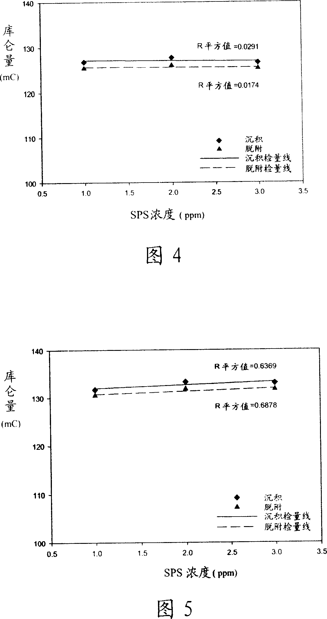
[0070] Please refer to Figure 4, which is a calibration curve diagram obtained by putting the SPS-adsorbed gold electrode into the electrolyte solution containing only sulfuric acid and copper sulfate for cyclic voltammetry scanning, and integrating the obtained polarization curve. By changing the concentration of SPS, observe whether the coulomb quantity obtained by the polarization curve integration will change with the increase of the SPS concentration. As shown in Figure 4, when the potential scan is performed in the electrolyte containing only sulfuric acid and copper sulfate, the coulomb quantity There is no obvious change with the different SPS concentrations, nor does it have a linear effect (R square value = 0.0291), so it cannot be used as the electrolyte for accelerator concentration analysis.

example 2

[0072] Please refer to Figure 5, which is a calibration curve diagram obtained by putting the SPS-adsorbed gold electrode into the electrolyte solution containing sulfuric acid, copper sulfate and chloride ions for potential scanning, and integrating the obtained polarization curve. As shown in Figure 5, the experimental results obtained in the electrolyte with more chlorine ions added are the same as when no chloride ions are added, and there is no linear effect (R square value = 0.6369), so it cannot be used as an accelerator concentration analysis. of electrolyte.

example 3

[0074] Please refer to Figure 6, which is to put the gold electrode adsorbed on SPS into the electrolyte solution containing sulfuric acid, copper sulfate and PEG for potential scanning, so as to observe the change of the current signal generated by the electrolyte solution added with PEG. As shown in Figure 6, as the concentration of SPS increases, the coulomb amount obtained by the polarization curve integration will decrease and show a linear relationship (R square value = 0.985), but the change of the coulomb amount is not obvious, so when electroplating Although there is a linear relationship when PEG is added to the liquid, the coulomb quantity does not change much, and it cannot be used as an electrolyte solution for accelerator concentration analysis, because if the coulomb quantity does not change much, the polarization measured when the accelerator concentration changes The curve will have the problem of insufficient accuracy, that is to say, the amount of Coulomb cha...


PUM


Abstract

A method for analyzing accelerant of electroplated copper includes placing copper electrode in electrolyte containing organic additives to let copper electrode absorb accelerant containing sulphur, using pure water to wash copper electrode absorbed with sulphur compound then placing copper electrode into deposit-electrolyte containing polyethylene glycol and chlorine ion and carrying out cathode circulation VA scan to deposit down copper metal, carrying out integration on obtained polarization curve to prepare out detection line. The deposit-electrolyte used in said method is also disclosed.

Description

technical field [0001] The invention relates to an analysis method of an electroplating copper accelerator, in particular to a method utilizing the selective adsorption of gold and sulfur-containing compounds contained in the accelerator, and the electrochemical reaction signal generated by the electrochemical reduction deposition of copper metal To analyze the concentration of the accelerator in the plating solution. Background technique [0002] With the development of electronic components towards miniaturization and complexity, there will be an increase in the number of wiring and shortening of the contact pitch, all of which need to be achieved by high-density circuit configuration and micro-hole technology. Therefore, the use of multi-layer circuit boards Then it became popular, and due to the improvement of circuit density and the increase of layers, the role of electroplating technology is becoming more and more important, and it has become a necessary technology for...

Claims


Application Information

Patent Timeline
IPC IPC(8): G01N27/26C25D21/12C25D3/38
Inventor 窦维平颜铭瑶黄晓君
Owner 欧恩吉亚洲股份有限公司
Why Eureka
Try Eureka