Digital controlled block cutting machine

The technology of last engraving machine and last head is applied in the field of numerical control last engraving machine, which can solve the problems of difficulty in meeting design requirements, large grinding workload and low precision.

Inactive Publication Date: 2007-08-01
郑豪迈
View PDF0 Cites 7 Cited by
  • Summary
  • Abstract
  • Description
  • Claims
  • Application Information

AI Technical Summary

Problems solved by technology

After the processing of the last head is completed, the redundant parts A and B of the last head need to be manually ground again. The grinding workload is heavy and the efficiency is low. One sample is one sample, and the accuracy is not high.
Since high-end shoes have very high requirements on the accuracy of the shoe last, it is difficult to meet the design requirements by manual grinding. How to solve this problem has always been a major technical problem in the shoe industry.

Method used


Image

  • Digital controlled block cutting machine
  • Digital controlled block cutting machine
  • Digital controlled block cutting machine

Examples


Embodiment Construction

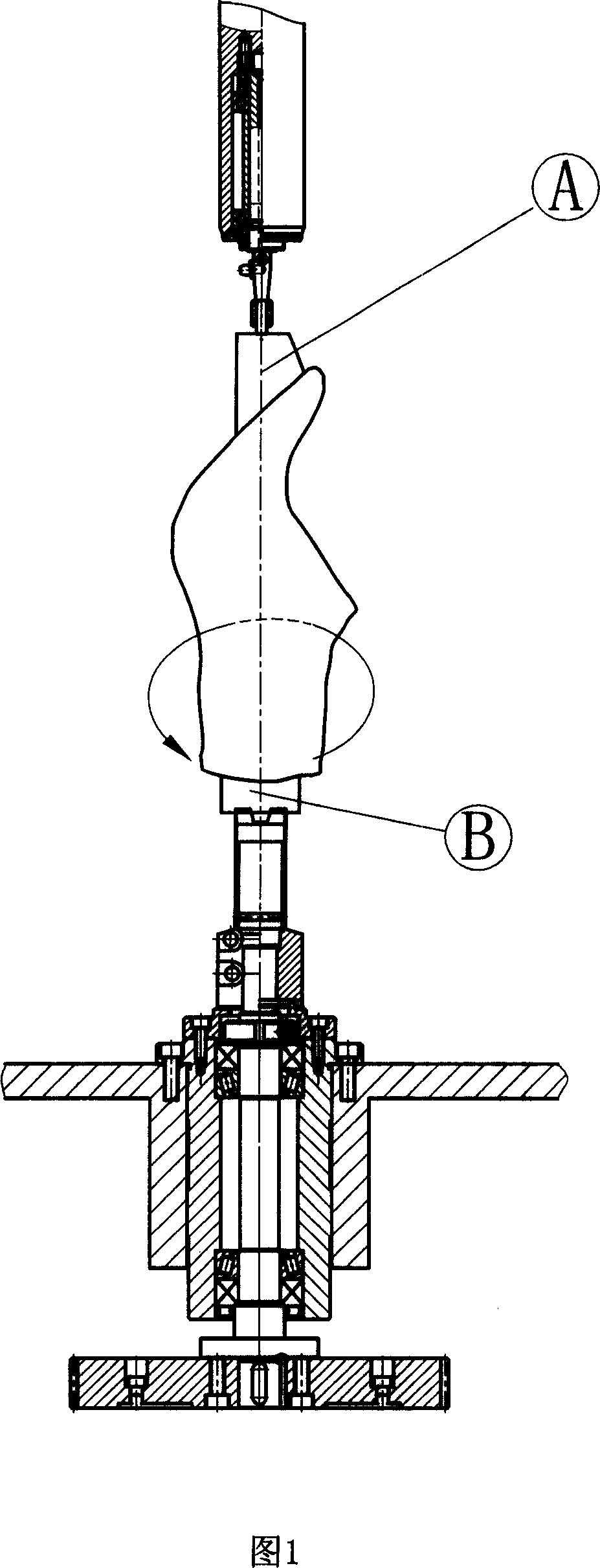
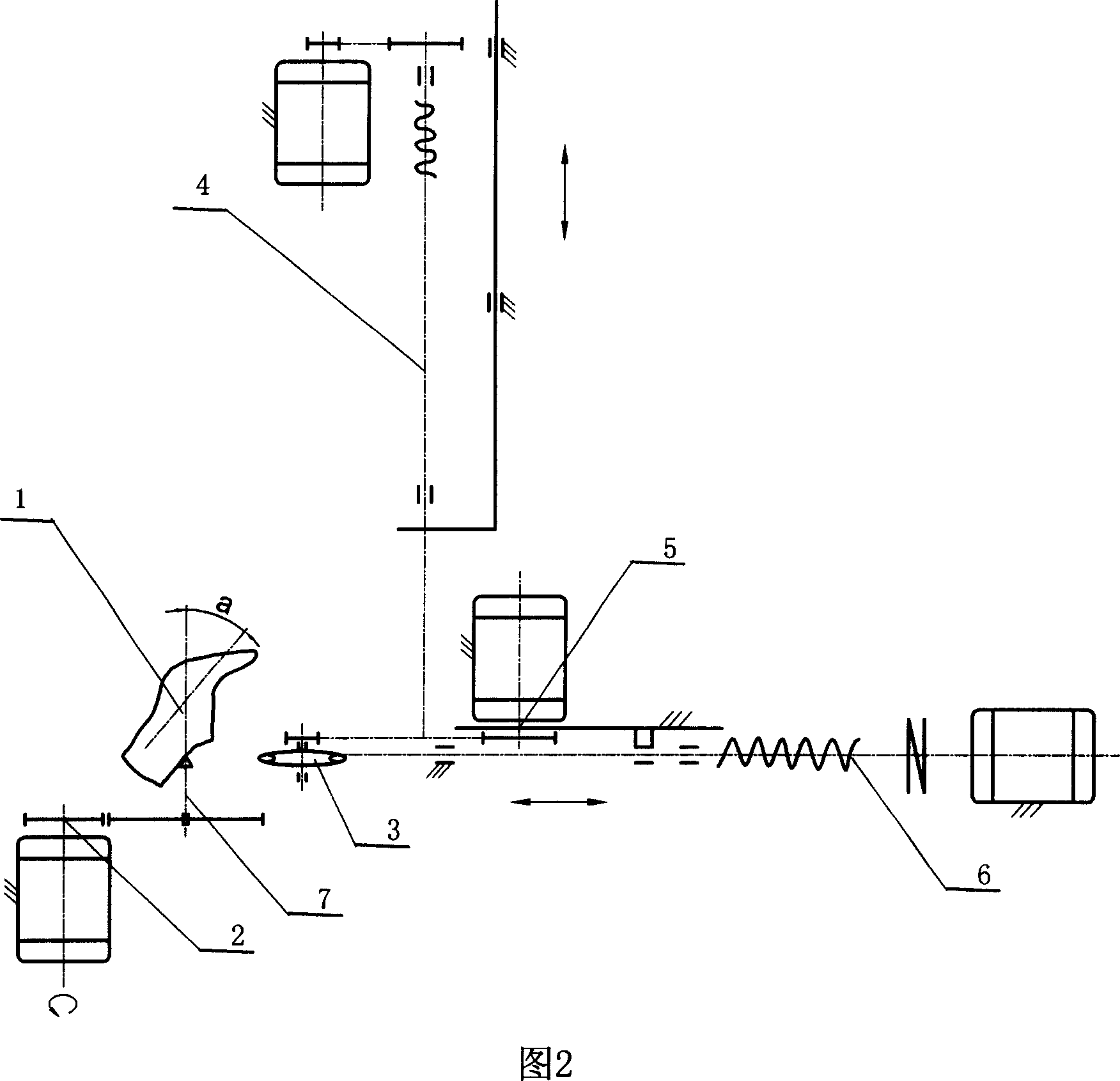
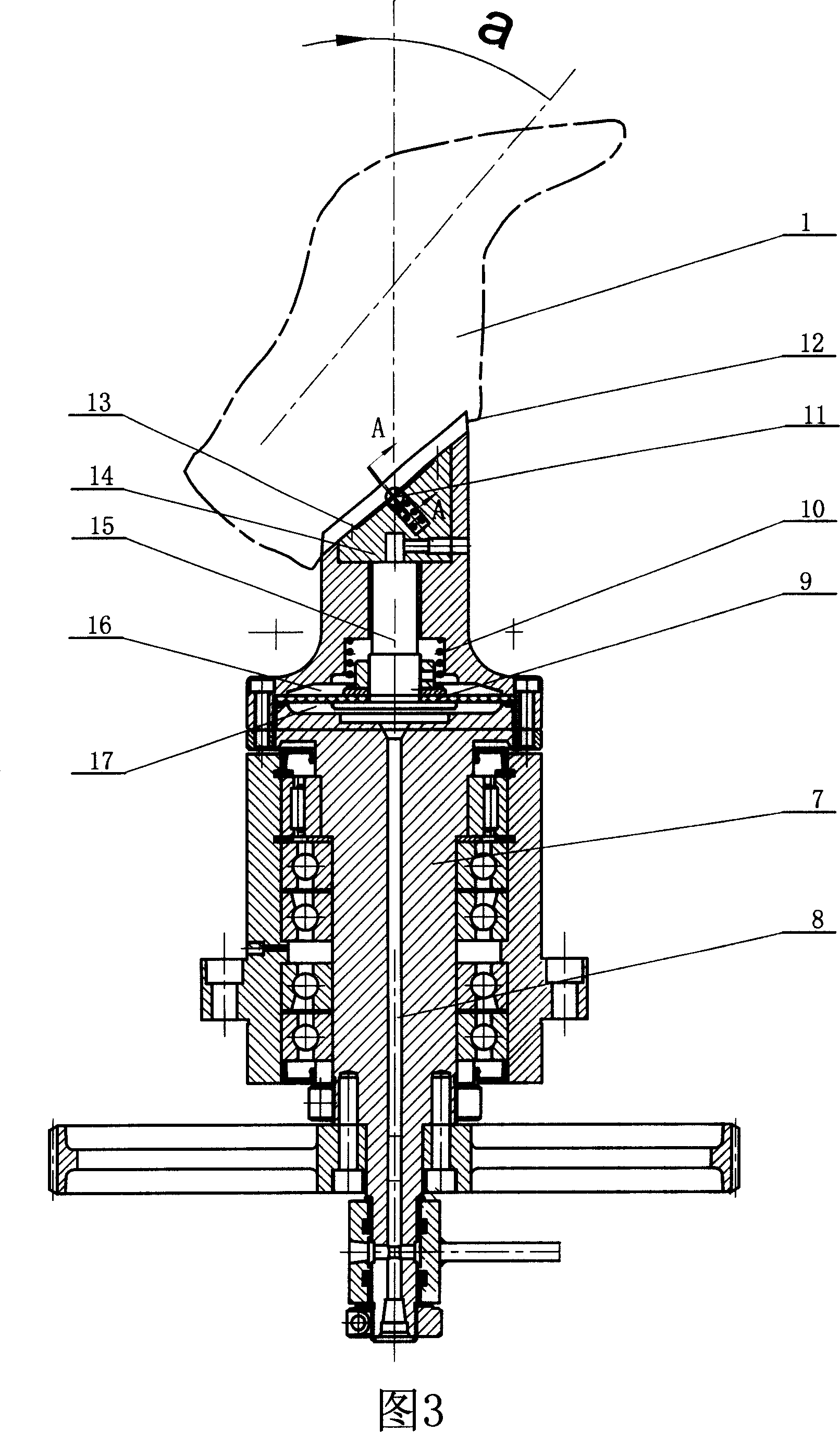
[0011] As shown in Figure 2, this embodiment includes a C-axis servo motor transmission system 2, a Y-axis servo motor transmission system 4, an X-axis servo motor transmission system 6, a cutterhead transmission system 5, a disc cutter 3, and a rotating shaft 7, wherein, The output end of the C-axis servo motor transmission system 2 is connected to the rotating shaft 7 . As shown in Figures 3-4, the top surface 13 of the rotating shaft is parallel to the last barrel surface 20 of the last blank 1, and forms a certain angle a with the center line of the rotating shaft, and the included angle a is 30°-50°, preferably 40°. A dovetail groove 18 is provided on the top surface 13 of the rotating shaft, which cooperates with the dovetail shaft 19 on the mouth surface of the last to form a last positioning device.

[0012] As shown in Figure 3 again, rotating shaft 7 is made of upper and lower two parts, separates with air bag 9 between the connection, forms upper and lower two cyli...


PUM


Abstract

The invention involves the shoemaking industry mechanical equipment, particularly relates to a digital control carving shoe-tree machine. It is characterized by: the top end of rotate axle is equipped with shoe-tree head blank positioning device and shoe-tree head blank clamping device which match with shoe-tree head tubular mouth surface. It aims at designing a digital control carving shoe-tree machine which can improve shoe-tree processing speed and precision. Compared with the prior technology, it has advantages of the shoe-tree shape is same before or after processing, accurate and perfect, saving materials, low cost, obvious efficiency improvement.

Description

technical field [0001] The invention relates to mechanical equipment in the shoemaking industry, in particular to a numerically controlled last-carving machine. Background technique [0002] Shoe last is the basic modeling mold used in shoemaking. At present, domestic and imported CNC last machines are used to process it. Among them, the upper and lower thimble structures are used to position and clamp the last blank workpiece. Tighten the last blank, and after the processing is completed, redundant parts A and B of the last will be produced at the head and tail thimbles of the last (as shown in Figure 1), which belong to the redundant parts of the last. After the processing of the last head is completed, the redundant parts A and B of the last head need to be manually ground again. The grinding workload is heavy, the efficiency is low, and the precision is not high. Since high-end shoes have very high requirements on the accuracy of the shoe last, it is difficult to meet t...

Claims


Application Information

Patent Timeline
Patent Type & Authority Applications(China)
IPC IPC(8): B27M3/20
Inventor 郑豪迈
Owner 郑豪迈
Why Eureka
Try Eureka