
Improved scroll-type fluid displacement apparatus with fully compliant floating scrolls

A fluid displacement and scroll technology, which is applied to the components of pumping devices for elastic fluids, sealing devices of piston pumps, and combination of rotary piston/oscillating piston pumps for elastic fluids, etc. It can solve the problem of manufacturing technology. Complex, high cost, limited service life and other issues

Active Publication Date: 2007-08-01
ADVANCED SCROLL TECHNOLOGIES (HANGZHOU) INC
View PDF2 Cites 20 Cited by
  • Summary
  • Abstract
  • Description
  • Claims
  • Application Information

AI Technical Summary

Problems solved by technology

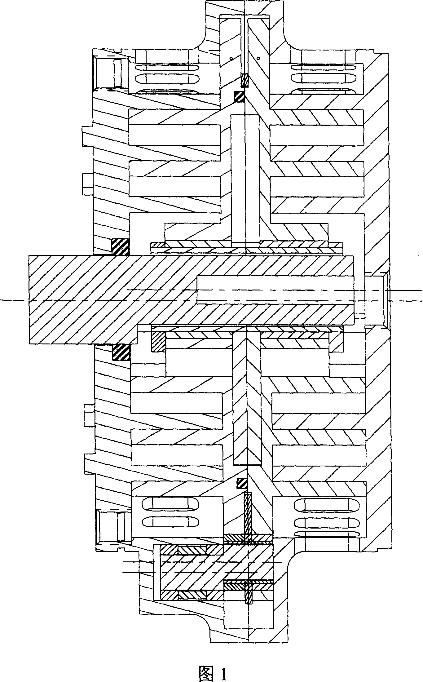
In these non-traditional push ball bearings, the balls roll in a small range equivalent to the orbiting radius of the scroll, so the bearing not only has a limited service life, but also is quite complicated in manufacturing technology and expensive

Method used


Image

  • Improved scroll-type fluid displacement apparatus with fully compliant floating scrolls
  • Improved scroll-type fluid displacement apparatus with fully compliant floating scrolls
  • Improved scroll-type fluid displacement apparatus with fully compliant floating scrolls

Examples


Embodiment Construction

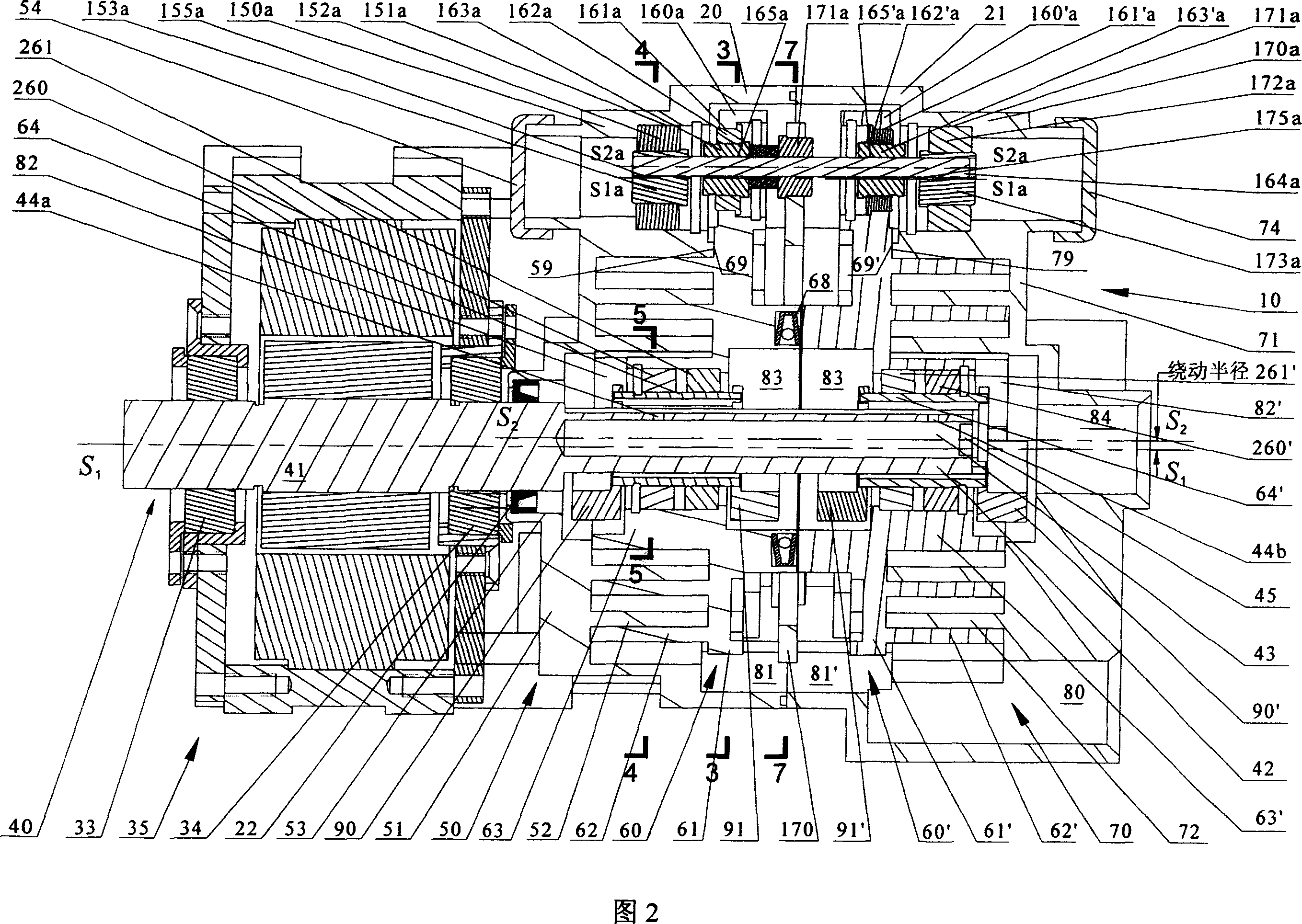
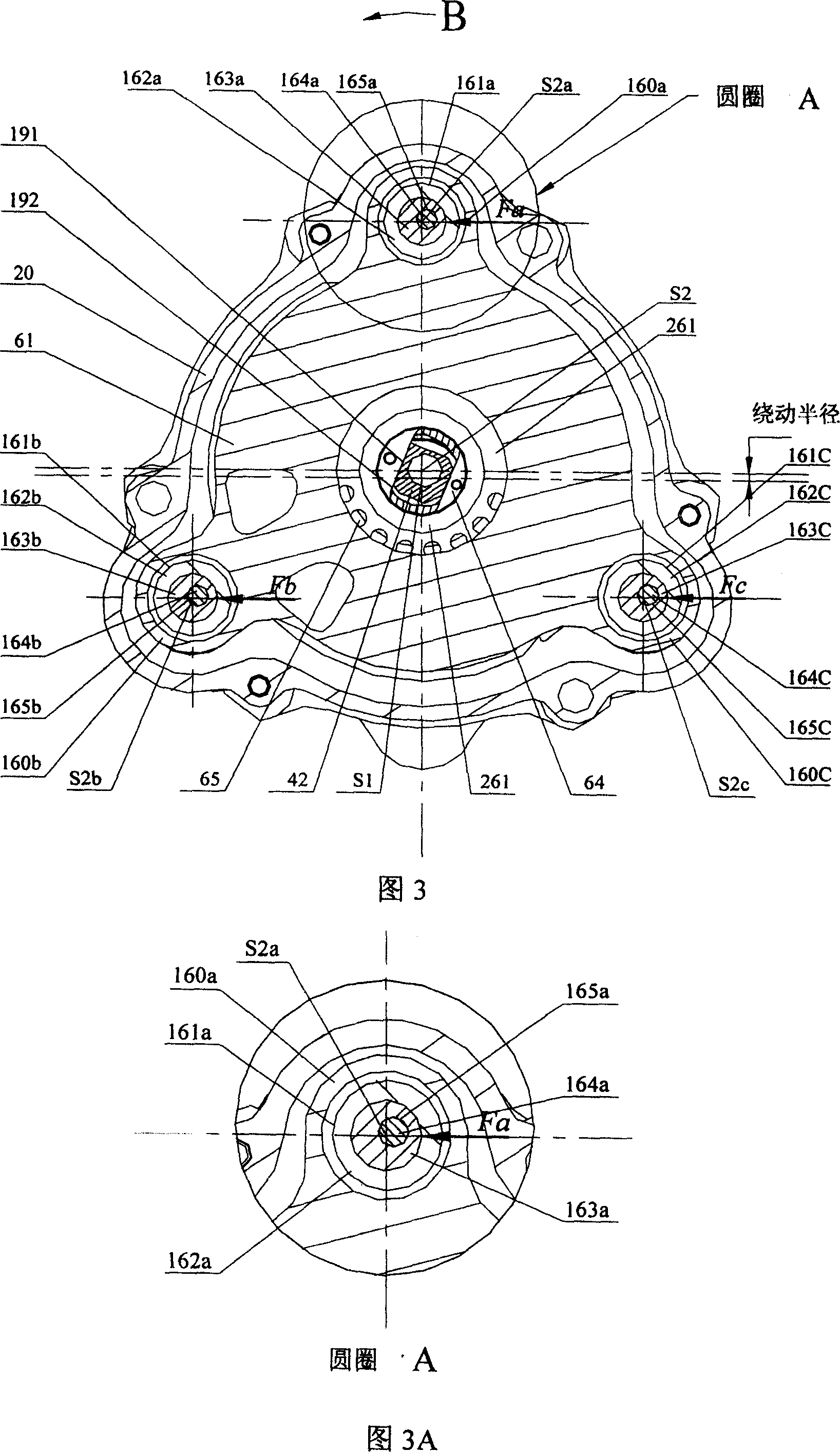
[0032] Referring to Figure 2, it depicts an omnidirectionally compliant suspended twin scroll air compressor with a CSPS mechanism. The compressor 10 includes a front casing 20 and a rear casing 21 . The central drive crankshaft 40 consists of a central shaft 41 and a crankpin 42 . The central shaft 41 is supported by the crankshaft bearings 33 and 34 and driven by the motor 35 to rotate about the axis S1-S1. The shaft seal 22 seals the high pressure gas in the central plenum 82 from the surrounding environment. The axial hole 43 is located in the middle of the crankpin 42, and is used to balance the centrifugal force generated by the crankpin 42 when the central crankshaft 40 rotates around the axis S1-S1. The axial hole 43 can also store lubricating grease. These greases can be gradually released through the small holes 44a and 44b to respectively lubricate the driving surface 191 of the crank pin 42 and the driven sliding surfaces 192 and 192' of the central driving join...


PUM


Abstract

A central drive shaft-sliding knuckle combined with a peripheral crank pin-swing link mechanism (CSPS) to provide an orbiting scroll with radial and axial compliant capability. The CSPS mechanism can be applied to both dual floating scroll and single floating scroll structures to improve performances of scroll devices, particularly in oil-free operations. In addition, an orbiting dual thrust ball bearing mechanism is provided to take thrust load in, for example, a floating scroll compressor with a CSPS mechanism.

Description

technical field [0001] The present invention is related to scroll-type volumetric fluid devices, more specifically, the present invention is a suspended scroll-type fluid device with omnidirectional compliance, ie, axial and radial compliance structures. Background technique [0002] Scroll pumps, compressors and expanders are well known machines. In this kind of machine, two spiral or involute scroll elements that mesh with each other are conjugated to each other and fixed on their respective end plates to form a moving scroll and a fixed scroll, respectively. The two scroll elements intermesh between the spiral scroll elements in line contact. [0003] At least one airtight chamber is formed by the pair of contact wires and the surfaces of the two end plates. When one of the scrolls, the movable scroll, makes a relative orbital motion, that is, a circular translation, relative to the other scroll, the contact line on the side wall of the helical element will move along t...

Claims


Application Information

Patent Timeline
Patent Type & Authority Applications(China)
IPC IPC(8): F01C17/06F04C18/02F04C27/00F04C29/00F04C29/02
CPCF01C17/06F04C23/001F04C29/0021F04C29/0057F16C2360/42
Inventor 倪诗茂
Owner ADVANCED SCROLL TECHNOLOGIES (HANGZHOU) INC
Learn More