High-frequency chirp radar directional diagram measuring method

A linear frequency modulation and measurement method technology, applied in radio wave measurement systems, antenna radiation patterns, instruments, etc., can solve the problems of complex hardware design and implementation, long measurement time, and high cost, so as to achieve simple implementation, reduce measurement costs, and reduce The effect of system complexity

Inactive Publication Date: 2007-08-08
WUHAN UNIV
View PDF0 Cites 23 Cited by
  • Summary
  • Abstract
  • Description
  • Claims
  • Application Information

AI Technical Summary

Problems solved by technology

In this scheme, the transponder needs to have the functions of signal reception, delay and transmission at the same time, and the hardware design and implementation are more complicated.
At the same time, the above scheme requires the transponder to stay in different directions for a certain period

Method used


Image

  • High-frequency chirp radar directional diagram measuring method
  • High-frequency chirp radar directional diagram measuring method

Examples


Embodiment Construction

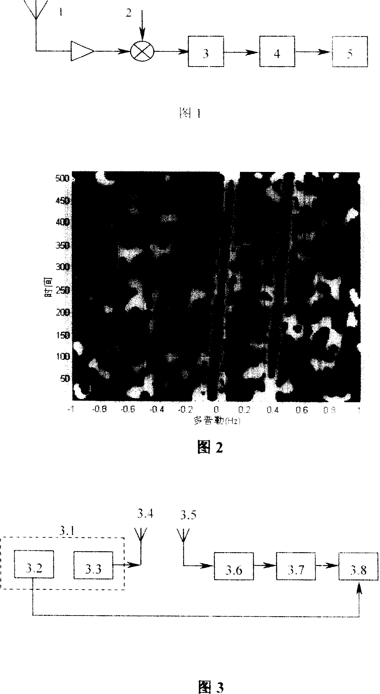
[0013] The key of the present invention is to use the time-frequency form of the single-frequency signal processed by the chirp radar receiver to extract the amplitude response of each antenna, and the instantaneous amplitude on each antenna of the radar is obtained by the average time-frequency distribution of the long-distance segment echo signal; The relative pattern of each antenna is obtained by one-to-one correspondence between the instantaneous amplitude ratio of each antenna to a certain reference antenna and the instantaneous azimuth angle of the platform.

[0014] Fig. 2 is a time-frequency distribution diagram of a typical single-frequency beacon signal, from which two obvious time-frequency ridges of the beacon signal can be seen. The instantaneous amplitude of the signal can be obtained through the time-frequency distribution, and the instantaneous amplitude ratio of each antenna relative to the reference antenna is obtained, and one-to-one correspondence with the ...


PUM


Abstract

A high frequency linear modulation radar direction measurement method, characterized by: in the radar far-field, emitting single-frequency continuous sinusoidal signal as a measurement beacon, and the beacon carrying platform uses radar for the center to move for directional scanning; processing time-frequency analysis to the echo received by each radar antenna, to obtain the transient response value of each antenna, and corresponding with the beacons of instantaneous position, which is the antenna direction map. The invention uses a simple single-frequency signal transmission to achieve the measurement and calibration of the direction map, and compared with the traditional transponders measurement method, it greatly reduces system complexity and measurement cost, with inexpensive way to improve the effectiveness of the direction map measurement.

Description

technical field [0001] The invention relates to a method for measuring and correcting the pattern of a high frequency linear frequency modulation radar antenna array by using a single frequency sine wave. Background technique [0002] Because of its unique over-the-horizon and all-weather detection capabilities, high-frequency (3-30MHz) radar has been widely studied and successfully applied to the measurement of ocean surface dynamic parameters, and can detect moving targets such as ships, aircraft and missiles in real time. High-frequency radars usually use a linear frequency modulation system. In the actual operating environment, the radar antenna pattern will be distorted due to the influence of the surrounding objects, which will cause the obtained orientation estimation to deviate from the true value and cause certain errors, or even errors. In order to obtain effective and high-precision target orientation estimation, it is necessary to measure the radar antenna patte...

Claims


Application Information

Patent Timeline
IPC IPC(8): G01R29/10G01S7/40
Inventor 周浩文必洋吴世才石振华
Owner WUHAN UNIV
Why Eureka
Try Eureka