Condensing heat exchanger

A heat exchanger and condensing technology, which is applied in the field of heat exchange devices, can solve the problems of inability to condense and release heat, large smoke loss, and reduce thermal efficiency, and achieve the effects of simple structure, reduction of harmful gases, and improvement of thermal efficiency.

Inactive Publication Date: 2007-08-15
CHENGDU QIANFENG HEAT EXCHANGER
View PDF0 Cites 12 Cited by
  • Summary
  • Abstract
  • Description
  • Claims
  • Application Information

AI Technical Summary

Problems solved by technology

The exhaust gas temperature is generally 160-250 °C, the water vapor in the flue gas is still in a superheated state, and cannot be condensed to release heat, and the heat is wasted with the flue gas discharge
At the same time, the high-temperature flue gas takes away a large amount of sensible heat, which together forms a large exhaust loss and reduces the thermal efficiency.

Method used


Image

  • Condensing heat exchanger
  • Condensing heat exchanger

Examples


Embodiment 1

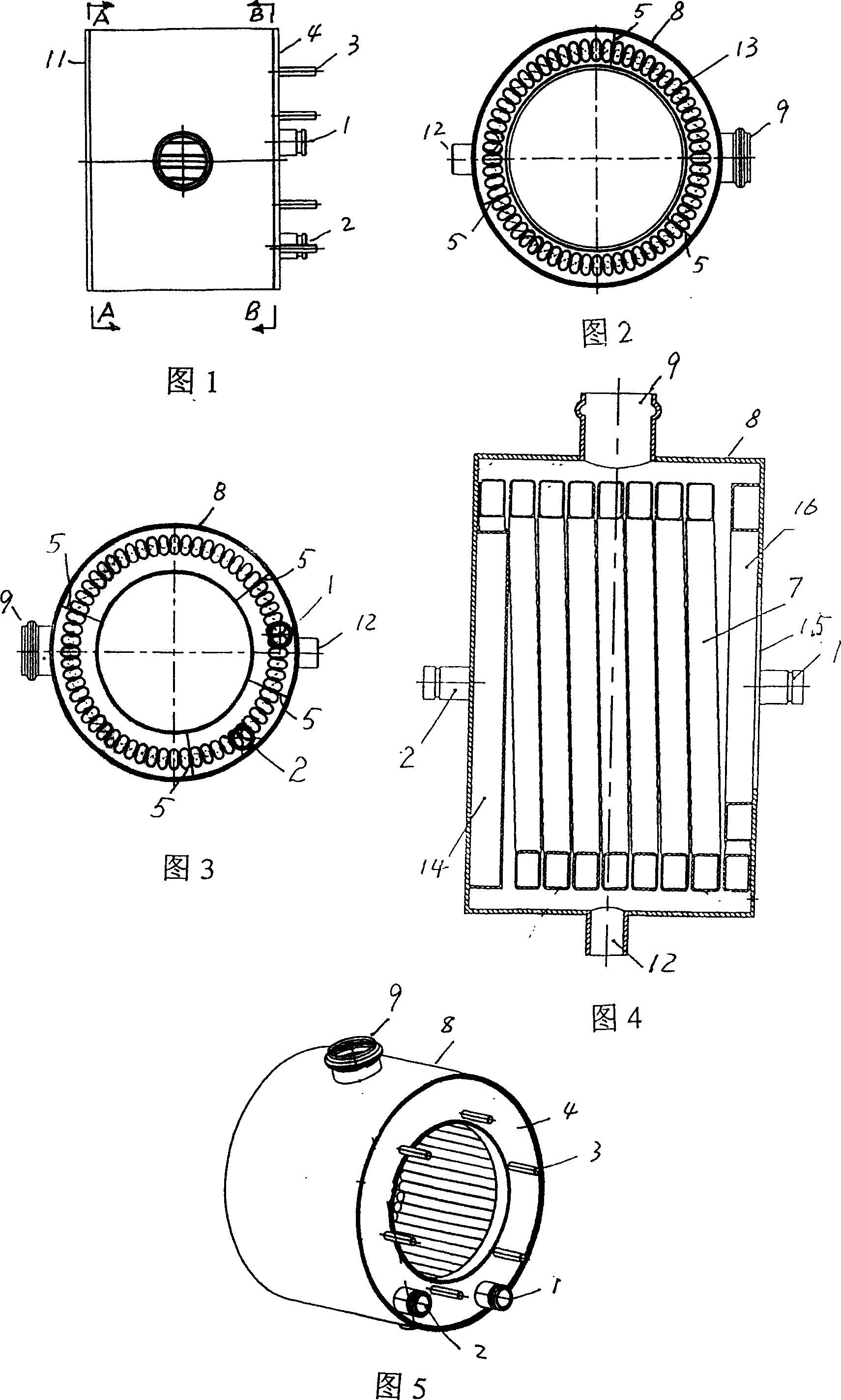
[0020] The condensing heat exchanger for a wall-mounted boiler consists of a heat-absorbing tube 7 spirally coiled to form a heat-absorbing cylindrical cylinder 13. The two ends of the heat-absorbing tube are respectively connected to the water outlet cavity 14 and the water inlet cavity 16. The cavity 14 and the water inlet cavity 16 are located in the shell 8, and there is a gap of 10-20mm between the outer wall of the cylinder body 13 and the inner wall of the shell 8, and the water outlet joint 2 and the water inlet joint 1 are connected to the water outlet cavity 14 and the water inlet cavity 16 respectively. Connection, the casing has a burner installation hole 15, through which the burner is installed in the barrel 13, the upper end of the casing is connected to the smoke outlet 9, and the lower end is connected to the condensed water outlet 12.

Embodiment 2

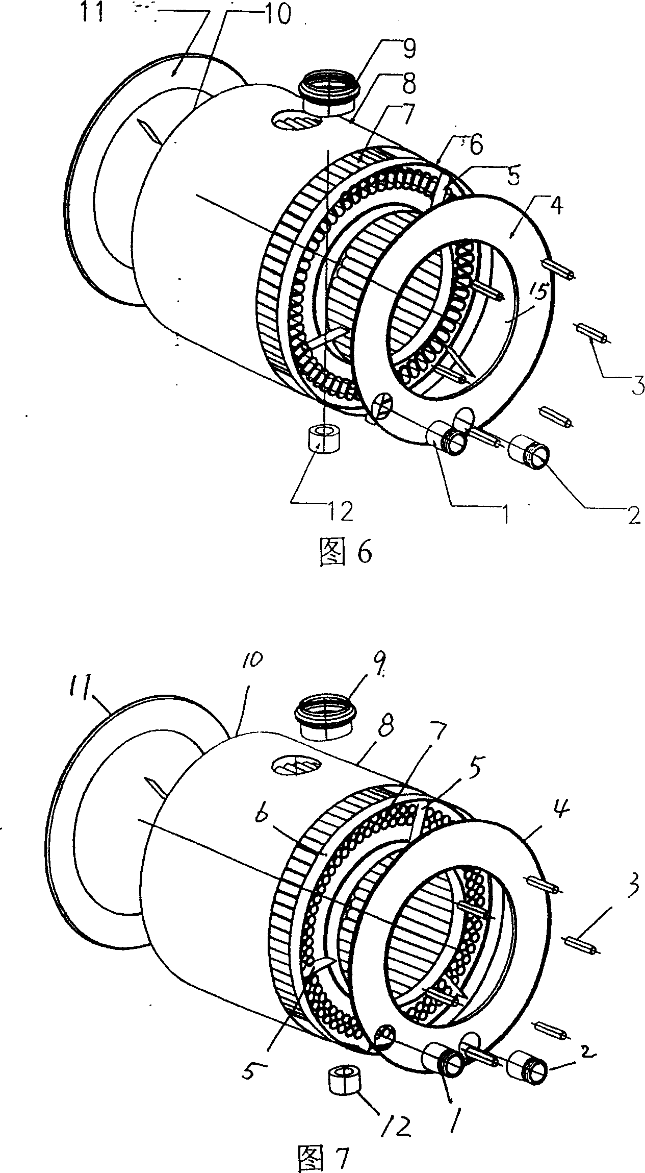
[0022] Some straight heat-absorbing pipes 7 are arranged in one layer or two layers to form cylinder body 13, arranged into one layer of heat-absorbing pipes with elliptical cross-section, and two-layer heat-absorbing pipes with circular cross-section. The two ends of the cylinder body respectively pass through the bottom surfaces of the front fixed plate 6 and the rear fixed plate 10 to be welded thereto. The front and rear fixing plates are ring-shaped, and their axial cross-section is groove-shaped. They are respectively welded with the ring-shaped front cover plate 4 and the circular rear cover plate 11 to form the front and rear water chambers. There are four water baffles 5 in the front water chamber. It is divided into four sub-water chambers, one of which communicates with the water inlet joint 1, and the other communicates with the water outlet joint 2. The hole in the middle of the front cover plate 4 is a mounting hole 15, and 6 burner mounting screws 3 are evenly d...


PUM


Abstract

The invention relates to a condensation heat exchanger, related to the heat exchanger of fuel burner, for resolving the problem as low thermal efficiency, wherein a horizontal cylinder frame (8) contains a cylinder (13) formed by coiling or axially arranging heat adsorption tube (7), the outer wall of the cylinder (13) and the inner wall of the frame (8) are arranged with a space between, two ends of the heat adsorption tube (7) are respectively connected with a water inlet connector (1) and a water outlet connector (2), the frame (8) is mounted with a smoke outlet (9) with a condensed water outlet (12) under, the cylinder (13) contains a burning room with a gas burner inside, and at least one of the frame (8) is arranged with a burner mounting hole (15).

Description

Technical field: [0001] The invention relates to a heat exchange device for a gas burner. Background technique: [0002] The heat exchange straight tubes of existing gas burners are arranged in one plane or in multiple parallel planes, the water in the straight tubes is directly heated by the fire head, and the smoke is discharged through the smoke exhaust port on the shell. The exhaust gas temperature is generally 160-250 °C, and the water vapor in the flue gas is still in a superheated state, unable to condense and release heat, and the heat is wasted with the flue gas discharge. At the same time, the high-temperature flue gas takes away a large amount of sensible heat, which together forms a large exhaust loss and reduces the thermal efficiency. What was invented: [0003] The object of the present invention is to provide a condensing heat exchanger with simple structure and high heat exchange efficiency. [0004] The present invention is achieved like this: [0005]...

Claims


Application Information

Patent Timeline
Patent Type & Authority Applications(China)
IPC IPC(8): F24H9/18F24H8/00
CPCY02B30/102Y02B30/00
Inventor 杨启明江涛郭全胜
Owner CHENGDU QIANFENG HEAT EXCHANGER
Why Eureka
Try Eureka