Non-contact mine ground pressure observing and estimating method

A mine pressure and non-contact technology, applied in force/torque/work measuring instruments, measuring devices, earthwork drilling and mining, etc., can solve the problem of weak forecasting function, inability to share the power supply and transmission channel of the safety monitoring system, and inability to share the KJ coal mine Issues such as the resources of the safety monitoring system, to achieve the effect of reducing the workload

Active Publication Date: 2007-08-22
CHINA UNIV OF MINING & TECH
View PDF3 Cites 30 Cited by
  • Summary
  • Abstract
  • Description
  • Claims
  • Application Information

AI Technical Summary

Problems solved by technology

Invention patent "Method and device for predicting gas-bearing coal rock concrete disasters, (ZL98111185.8)" through non-contact monitoring of the electromagnetic radiation signal generated when the loaded coal rock mass deforms and ruptures and its short-term (several minutes) change law, forecasting The danger of coal and rock dynamic disasters such as coal and gas outburst and rock burst reflects the instantaneous state of a certain stage in the evolution process of coal and rock dynamic disasters. It has not realized continuous and uninterrupted monitoring and forecasting, and cannot share KJ Resources for Coal Mine Safety Monitoring Systems
[0010] The utility model patent "Electromagnetic Radiation Monitoring Device for Coal and Rock Dynamic Disasters, Patent No. ZL01272808.X" can continuously monitor and warn the danger of coal and rock dynamic disasters when an external power supply is connected, but it cannot be connected with the KJ series coal mine safety monitoring system. Share the power supply and transmission channel of the safety monitoring system, separate wiring and separate power supply are required to realize remote monitoring, and the forecasting function is weak

Method used


Image

  • Non-contact mine ground pressure observing and estimating method
  • Non-contact mine ground pressure observing and estimating method
  • Non-contact mine ground pressure observing and estimating method

Examples


Embodiment Construction

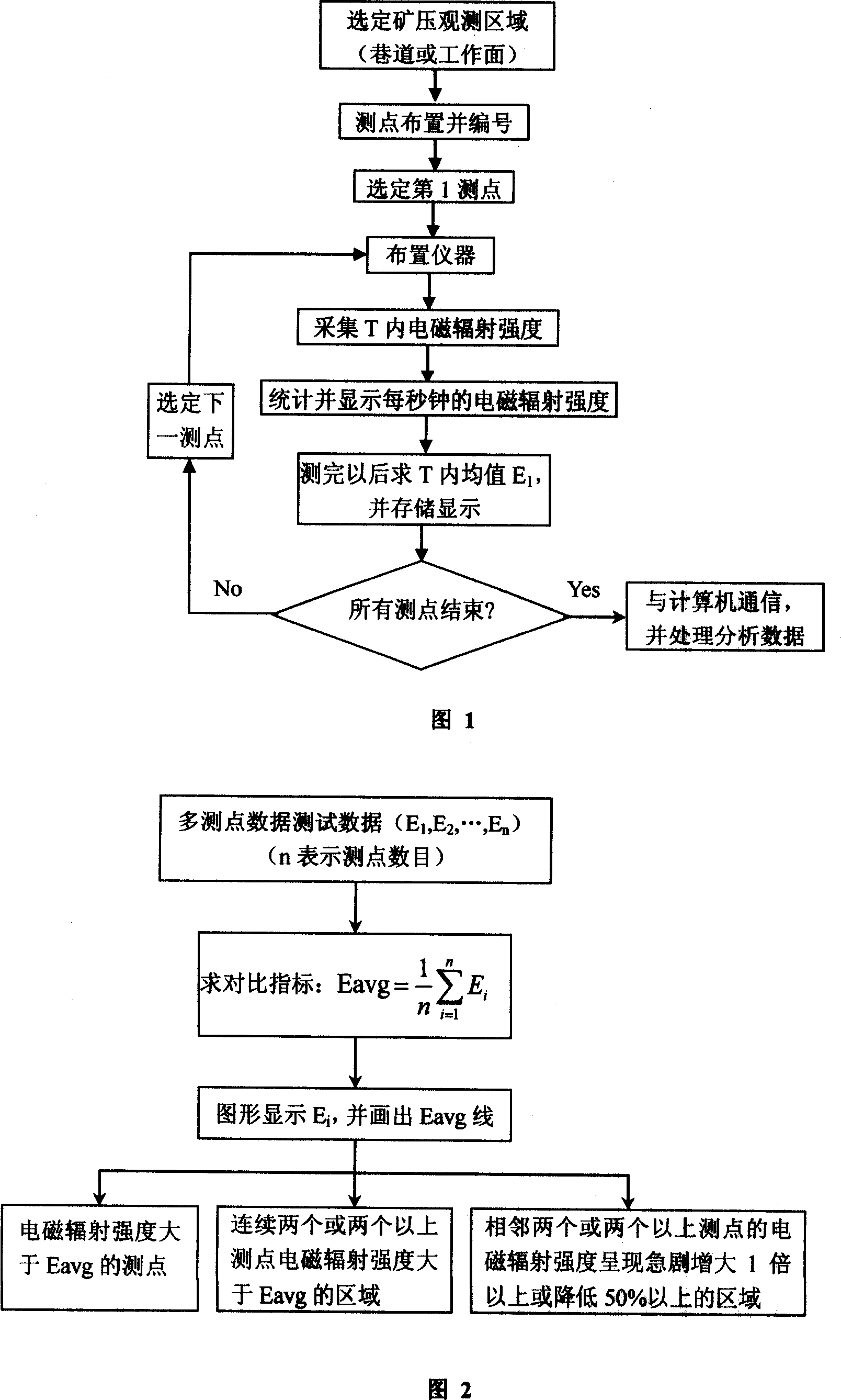
[0035] The flow chart of non-contact mine pressure observation is shown in Figure 1. Before adopting mobile and non-contact mine pressure observation, the area to be monitored must be selected first, such as the transportation lane of a certain mining face is selected as the observation and evaluation area, and then the measuring points are arranged (1~n measuring point), the measuring point layout spacing is L 1 (The range is generally 1 to 10 meters). When monitoring, the effective receiving direction of the directional receiving electromagnetic antenna should be aligned with the measuring point, so that the axial direction of the antenna is perpendicular to the outer surface of the measuring point, and the antenna should be fixed. The distance between the antenna and the measured coal rock wall is L 2(The range is 0.1 ~ 1 meter). The principle of determination is to include the monitored measuring point area just within the 60-degree opening direction of the antenna, as s...


PUM


Abstract

The invention is a non-contact mine pressure observing and evaluating method, relating to a technique of monitoring and evaluating relative stress state of mine digging space or tunnel wall rock by non-contact monitoring the electromagnetic radiation information generated by loaded coal and rock, and the observing method: firstly selecting a region to be monitored, aligning the valid receiving direction of an oriented receiving electromagnetic antenna to an test point and obtaining Ei after test and testing until all test points are tested. And the evaluating method: index of mine pressure evaluation adopts average values Ei of electromagnetic radiation strengths of coal and rock, and calculating average value Eavg of all Ei; displaying the test results Ei in figure, and when the obtained electromagnetic radiation strength of a test point is higher than Eavg, the test point is evaluated as a high stress point; a region with two or more continuous test points whose electromagnetic radiation strengths are all higher than Eavg is evaluated as a high stress region; a region with two or more adjacent test points whose electromagnetic radiation strengths sharply increase by twice above or sharply decrease by above 50%, is evaluated as a high stress gradient region.

Description

technical field [0001] The invention relates to a technology for monitoring and evaluating the relative stress state of mine excavation space or tunnel surrounding rock through non-contact monitoring of electromagnetic radiation information generated by loaded coal rock mass, belonging to the technical field of mine pressure monitoring and evaluation. Background technique [0002] In the process of human mining, the mining activities destroy the stress balance state of the original rock, causing the redistribution of the ground stress around the mining space. Around the stope and mining roadway, due to the stress of the surrounding rock, the surrounding rock is deformed, destroyed and moved, and the roof collapses and comes under pressure, the roof and the floor move closer, the support is loaded and shrinks, and the fracture occurs. , There may also be dynamic phenomena such as coal and gas outburst, water inrush, and rock burst. [0003] Therefore, monitoring and evaluati...

Claims


Application Information

Patent Timeline
Patent Type & Authority Applications(China)
IPC IPC(8): G01V3/12G01L5/00G01N27/00E21B49/00
Inventor 王恩元何学秋王云刚刘晓斐李忠辉刘贞堂窦林名
Owner CHINA UNIV OF MINING & TECH
Why Eureka
Try Eureka