Magnetic resonance receive coils with compact inductive components

A technology of magnetic resonance and magnetic resonance imaging, which is applied in the direction of magnetic resonance measurement, measurement of magnetic variables, measurement devices, etc., can solve the problems of increased coil weight, which is not conducive to wearable coils, etc., to achieve the effect of simplifying manufacturing

Inactive Publication Date: 2007-08-22
KONINKLIJKE PHILIPS ELECTRONICS NV
View PDF0 Cites 11 Cited by
  • Summary
  • Abstract
  • Description
  • Claims
  • Application Information

AI Technical Summary

Problems solved by technology

This bulky sensing component also adds weight to the coil, which is not conducive to wearable coils

Method used


Image

  • Magnetic resonance receive coils with compact inductive components
  • Magnetic resonance receive coils with compact inductive components
  • Magnetic resonance receive coils with compact inductive components

Examples


Embodiment Construction

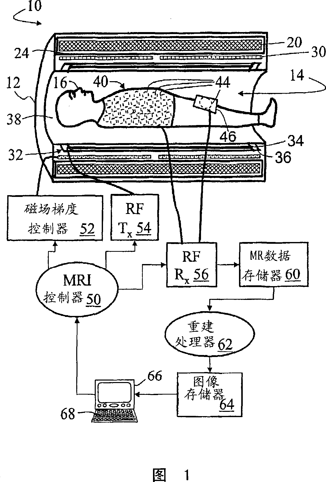
[0022] 1, the magnetic resonance imaging scanner 10 includes a housing 12 that defines a substantially cylindrical scanner hole 14 in which a related imaging object 16 is disposed. The main magnetic field coil 20 is arranged in the housing 12 and generates a main magnetic field B whose direction is substantially parallel to the central axis of the scanner hole 14 0 . The main magnetic field coil 20 is usually a superconducting coil provided in the cryogenic shield 24, but a resistive main magnet may also be used. The housing 12 also houses or supports a magnetic field gradient coil 30 for selectively generating a magnetic field gradient in the hole 14. The housing 12 also contains or supports a small-profile integral radio frequency body coil 32 for selectively exciting magnetic resonance. In the illustrated embodiment, the coil 32 is a small-profile coil formed by conductive traces 34 provided on a cylindrical substrate 36. The small profile of the coil 32 limits the amount of sp...


PUM


Abstract

A low profile radio frequency coil (32, 44, 441, 442, 443) for use in a magnetic resonance imaging system includes a low profile antenna (34, 102, 202, 302) that is configured to resonate at about a magnetic resonance frequency of the magnetic resonance imaging system. A generally planar inductor (110, 112, 210, 240, 310) is electrically connected or coupled with the low profile antenna. The generally planar inductor provides selected frequency filtering of a radio frequency signal received by or transmitted by the low profile antenna.

Description

Technical field [0001] The following content is especially applicable to radio frequency coils for magnetic resonance imaging. However, this content also applies to general radio frequency coils. Background technique [0002] Radio frequency coils are used in magnetic resonance imaging systems to excite and receive magnetic resonance. Radio frequency coils include antennas that are configured to resonate near the magnetic resonance frequency, and coil electronics that perform various functions, such as tuning, decoupling the receiving antenna during the transmit phase, and providing the received magnetic resonance signal. Pre-amplification, provide RF signal matching between antenna and coil cable, trap common mode signal or provide other selected frequency filtering. [0003] In order to provide close coupling of the radio frequency coil with the patient or other imaging object, the surface coil is sometimes placed close to or actually in physical contact with the imaging object...

Claims


Application Information

Patent Timeline
Patent Type & Authority Applications(China)
IPC IPC(8): G01R33/36
CPCG01R33/3628G01R33/3657G01R33/34007
Inventor M·瓦恩特耶斯M·J·范赫尔沃尔特S·M·克尼希T·克米列夫斯基
Owner KONINKLIJKE PHILIPS ELECTRONICS NV
Why Eureka
Try Eureka