
Air cleaning system in closed cabin and the control method

An air purification system and purification system technology, applied in chemical instruments and methods, separation methods, air quality improvement, etc., can solve the problems of poor air purification effect, complex structure, and large volume of combustion devices

Inactive Publication Date: 2007-09-19
陶好训
View PDF0 Cites 18 Cited by
  • Summary
  • Abstract
  • Description
  • Claims
  • Application Information

AI Technical Summary

Problems solved by technology

Both of these two treatment methods have certain prominent shortcomings. The working temperature of the catalytic combustion method is as high as 315°C, and the power consumption and water consumption are relatively large. For example, the treatment air volume is 800m 3 The maximum power consumption of the combustion device per hour is 50kw, and the consumption of cooling water at 6°C is 2t / h. The power consumption of cooling water is not included in the above power consumption. The volume of the combustion device is large (about 2.85m 3 ), the structure is complex, and it is difficult to achieve perfect heat preservation to reduce the surface temperature of the device
Therefore, the heat loss on the surface of the device is large, which has a great influence on the ambient temperature in the cabin.
If the large flow rate is 800m 3 The air heated per hour to 315°C not only consumes a lot of power, but also causes a lot of secondary pollution, which is not conducive to the control of the air quality and environmental conditions in the cabin; the main problem with the method of adsorbing and purifying air with activated carbon is its short service life. Difficult to replace, high cost of use, can not be regenerated and reused, often overdue use and cannot be replaced in time, resulting in poor treatment and purification of air, which is a defect in the prior art

Method used


Image

  • Air cleaning system in closed cabin and the control method

Examples


Embodiment Construction

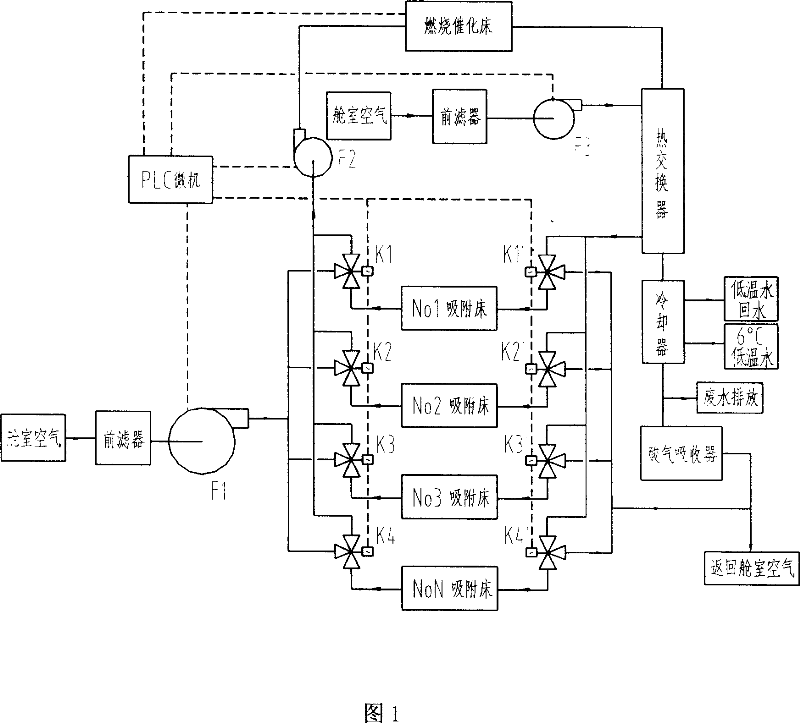
[0013] The present invention is made up of main air purification system, auxiliary air purification system and connection combination system, is characterized in that main air purification system is air adsorption purification system; auxiliary air purification system is catalytic combustion air purification system; connection combination system connects main air purification system It is organically connected with the auxiliary air purification system to form an air purification system that combines adsorption and catalytic combustion. The combined system can also be called a desorption regeneration system.

[0014] The main air purification system of the present invention is composed of a pre-filter, a fan armor and a multi-unit activated carbon fiber adsorption bed, and the number of the adsorption beds is set according to the required parameters; , resistance, weight of loaded adsorption material, adsorption time, desorption time and other settings, generally 3-7 unit adsor...


PUM


Abstract

A closed-in compartment air cleaning system and a control method thereof are disclosed, wherein the system id composed of three subsystems: a main air cleaning system, namely called as the adsorbing air cleaning system; a vice air cleaning system, namely called as the catalytic combustion air cleaning system; a linking combinatorial system, also called as the desorption reproduction system, having the advantages of combining the adsorption, the desorption, the catalytic combustion, to integrate the closed-in compartment air cleaning perfect system. The system adopts PLC microcomputer planed as a whole to control each link, which is of high efficiency, energy saving, environmental protection and sanitation. The air cleaning system and the control method can be designed into the air cleaning device with different specification according to the requirement, which can be used in the nuclear submarine, the AIP submarine, the conventional submarine, the manned spacecraft, the underground anti-aircraft defense and the air cleaning process of the air standard plant, and is an ideal closed-in compartment air cleaning system and a control method.

Description

1. Technical field: [0001] The invention relates to an air purification system and a control method thereof, in particular to an air purification system and a control method for a closed cabin, which is suitable for air purification treatment of submarines, space manned spaceships and underground air defense facilities. 2. Background technology: [0002] At present, there are two kinds of air purification methods that are actually used in airtight cabins polluted by organic matter. The first is the catalytic combustion method, that is, the catalytic combustion system; air filter. Both of these two treatment methods have certain prominent shortcomings. The working temperature of the catalytic combustion method is as high as 315°C, and the power consumption and water consumption are relatively large. For example, the treatment air volume is 800m 3 The maximum power consumption of the combustion device per hour is 50kw, and the consumption of cooling water at 6°C is 2t / h. The ...

Claims


Application Information

Patent Timeline
IPC IPC(8): A62B11/00B63G8/36B64G1/48B01D1/04B01D53/86
CPCY02A50/20
Inventor 陶好训陶志勇陶志杰罗沙
Owner 陶好训
Learn More