Small-sized Wind power generator and its assembly method

A wind-driven generator, a small-scale technology, applied in the direction of wind-driven engine, wind-driven motor combination, wind power generation, etc., can solve the problems of increased motor weight, reduced power generation effect, large axial size of the motor, etc.

Inactive Publication Date: 2007-09-19
GUANG ZHOU HYENERGY TECH
View PDF1 Cites 8 Cited by
  • Summary
  • Abstract
  • Description
  • Claims
  • Application Information

AI Technical Summary

Problems solved by technology

The disadvantage of this kind of generator is that the axial size of the motor is large, the volume of the motor is large, and the weight of the motor increases, which will increase the counterweight of the rear seat and tail rudder of the generator accordingly, and increase the starting torque when the motor starts, which is suitable for small power generators. machine, it will greatly reduce the power generation effect
In addition, both ends of the motor housing are provided with end cover structures for installing bearings, and the concentricity requirements of the mounting holes for installing bearings on the end covers at both ends must be very high, which will improve processing accuracy and increase processing costs.
[0003] The existing assembly method of small generators is to fix the rotor on the rotor shaft first, and then install other structures. This assembly method cannot meet the assembly process and mass production of some special structures.

Method used


Image

  • Small-sized Wind power generator and its assembly method

Examples


Embodiment Construction

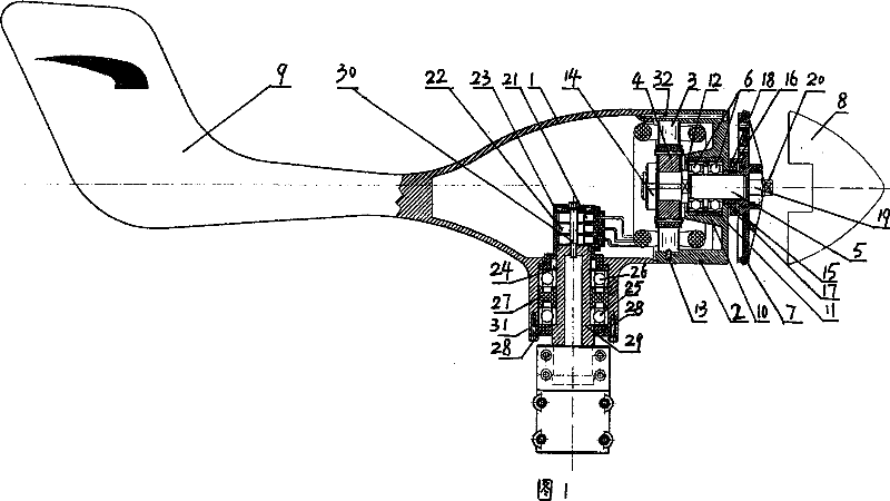
[0023] As shown in Figure 1, a small-sized wind power generator includes a rear seat 1, a motor casing 2, a stator 3, a rotor 4, a stainless steel rotor shaft 5, two first ball bearings 6 of type 205 supporting the rotor shaft 5, The hub disc 7 and the front cover 8 are equipped with wind rotor blades (not shown) on the front cover 8, and a tail rudder 9 is provided on the rear seat 1.

[0024] A conical first boss 10 is provided on the inner end surface of the motor casing 2 away from the rear seat 1 and toward the rear seat 1 , and the first boss 10 is coaxial with the motor casing 2 . A mounting hole for installing the first ball bearing 6 is provided in the first boss 10 , and the first ball bearing mounting hole is coaxial with the first boss 10 . A wear-resistant rubber ring 11 is provided along the inner side wall of the first ball bearing installation hole, and the two first ball bearings 6 are installed in the rubber ring 11 . On the inner sidewall in the first ball ...


PUM


Abstract

Provided is a small power plant which comprises a rear seat, a motor case, a stator, a rotor, a rotor shaft, a first bearing for supporting the rotor shaft, a wheel hub disk, and a front cover. A first lug boss is arranged on an inner end surface which is apart from one end of the rear seat and orients towards the rear seat. An mounting aperture for mounting the first bearing is arranged in the first lug boss. The first bearing for supporting the rotor shaft is arranged only on one side of the stator and rotor. One end of the first bearing is blocked by the end surface of the motor case, and the other end is blocked by a retaining ring. The assembly method of the power plant includes pressing the stator onto the motor case, thereafter mounting the retaining ring, and pressing the stator onto the motor case followed by pressing the rotor onto the rotor shaft. The advantages of power plant provided in present invention include decreased motor axial size, volume, weight and balance weight of rear seat tail rudder, reduced start torque of starting wind turbine power plant, improved electricity generating effect, reduced processing precision and cost. The assembly method of this invention is simple and adapt to mass production.

Description

technical field [0001] The invention relates to a small wind power generator and an assembly method thereof, in particular to a small wind power generator which can be used for wind power generation and an assembly method thereof. Background technique [0002] Existing small wind power generators all have bearings installed on both sides of the generator rotor and stator, which must be provided with an end cover structure supporting the bearings on both sides of the generator rotor and stator. For example, the patent number is 200620055463.9, and the name is a technical solution disclosed by a small wind power generator. It is disclosed that bearings are installed at both ends of the generator shaft, and end cover structures for installing bearings are arranged at both ends of the motor casing, that is, bearings are installed on both sides of the generator rotor and stator. The disadvantage of this kind of generator is that the axial size of the motor is large, the volume o...

Claims


Application Information

Patent Timeline
Patent Type & Authority Applications(China)
IPC IPC(8): H02K7/18H02K5/16H02K5/173H02K5/14H02K13/00F03D9/00F03D9/25
CPCY02E10/725Y02E10/72Y02P70/50
Inventor 俞红鹰
Owner GUANG ZHOU HYENERGY TECH
Why Eureka
Try Eureka