Switching voltage regulator with low current trickle mode

A technology of voltage regulators and switching regulators, applied in the direction of adjusting electrical variables, control/regulation systems, high-efficiency power electronic conversion, etc., can solve problems such as power consumption

Active Publication Date: 2007-09-19
MICREL
View PDF1 Cites 36 Cited by
  • Summary
  • Abstract
  • Description
  • Claims
  • Application Information

AI Technical Summary

Problems solved by technology

Any switching of the transistor consumes power by charging and discharging its gate
[0010] Bipolar transistors also have a parasitic capacitance where the regulator takes power to turn the bipolar transistor on and off

Method used


Image

  • Switching voltage regulator with low current trickle mode
  • Switching voltage regulator with low current trickle mode
  • Switching voltage regulator with low current trickle mode

Examples


Embodiment Construction

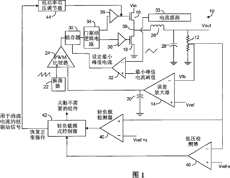
[0020] FIG. 1 illustrates a voltage mode voltage regulator 10 incorporating a light load current mode feature, according to an embodiment of the present invention.

[0021] A resistor divider 12 connected to the output terminal of the regulator provides a feedback voltage Vfb to an error amplifier 14 . A stable reference voltage Vref is provided to a second input of the error amplifier 14 . Regulator 10 regulates the duty cycle of switching transistors 16 and 18 to keep Vfb at the same level as Vref.

[0022] The output of error amplifier 14 is a current that adds and subtracts the charge in capacitor 20 to relate the capacitor 20 voltage to the duty cycle required to achieve the regulated voltage. A higher capacitor voltage corresponds to a higher duty cycle. In a voltage mode regulator, the duty cycle is equal to the ratio of Vout to Vin. Vin can be a battery voltage.

[0023] The capacitor voltage is compared to a sawtooth oscillator 22 signal. A pulse width modulation...


PUM


Abstract

For load currents greater than a threshold current, the voltage regulator operates in a conventional manner by fully turning on and off one or more switching transistors (16) at a duty cycle necessary to maintain the output voltage a regulated voltage. Upon a load current below a threshold being detected (76), a controller stops the switching of the transistor(s) and applies a reduced drive signal (44) to the high side transistor so as to apply a constant trickle current to the load. Unnecessary components are shut down to save power (42). When the output voltage falls below a threshold (46), the normal switching routine is resumed to recharge the regulator's output capacitor (28) to a certain level, and the regulator once again enters the light load current mode. By not completely shutting down the transistors at light load currents, as in done in a conventional intermittent-operation mode, there is lower power loss by less frequent switching of the transistor(s).

Description

technical field [0001] The present invention relates to voltage regulators, and more particularly to a technique for operating a voltage regulator in a light load current mode to save energy. Background technique [0002] Switching voltage regulators are well known. In one type of buck switching regulator, a high-side switching transistor connected to a supply voltage is switched between fully on and fully off at a controlled duty cycle and at a fixed frequency, wherein the duty cycle is regulated In order to keep the output voltage at a specified regulation voltage. The pulsating currents from the transistor switching are smoothed out by a filter usually consisting of a series of inductors and a capacitor to ground. A diode or synchronous rectifier is in series with the high-side transistor and is usually connected to ground. When the high side transistor is off, the current flowing through the powered inductor is conducted by the diode or the synchronous rectifier. The...

Claims


Application Information

Patent Timeline
Patent Type & Authority Applications(China)
IPC IPC(8): H02M3/156
CPCY02B70/16H02M2001/0032H02M3/156Y02B70/10H02M1/0032G05F1/10G05F1/38
Inventor 马修·温查尔斯·维恩
Owner MICREL
Why Eureka
Try Eureka