Heat recovery type water chilling unit
A chiller and heat recovery technology, applied in heat recovery systems, energy-saving heating/cooling, energy recovery systems for ventilation and heating, etc., can solve problems such as compressor oil leakage, compressor damage, burnout, etc., to achieve safe and reliable operation , save operating costs and reduce pollution
- Summary
- Abstract
- Description
- Claims
- Application Information
AI Technical Summary
Problems solved by technology
Method used
Image

Examples
Embodiment Construction
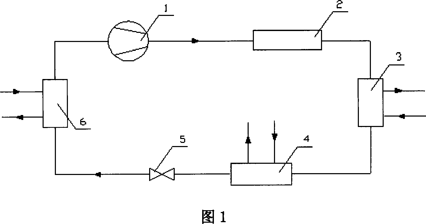
[0015] Shown in accompanying drawing 1 is an embodiment of the heat recovery chiller, the heat recovery chiller is composed of a compressor 1, an oil separator 2, a hot water heat exchanger 3, a condenser 4, a throttling device 5, and an evaporator 6 and connecting pipelines, etc., wherein the hot water heat exchanger 3 is connected in series between the oil separator 2 and the condenser 4. The high-temperature refrigerant gas coming out of the oil separator 2 enters the hot water heat exchanger 3, exchanges heat with the application water flowing through the heat exchanger 3, is initially cooled and enters the condenser 4; The application water absorbs the heat of the high-temperature refrigerant and then heats up and outputs it as domestic or production hot water. The hot water heat exchanger adopts any one of plate type, shell and tube type and casing type.
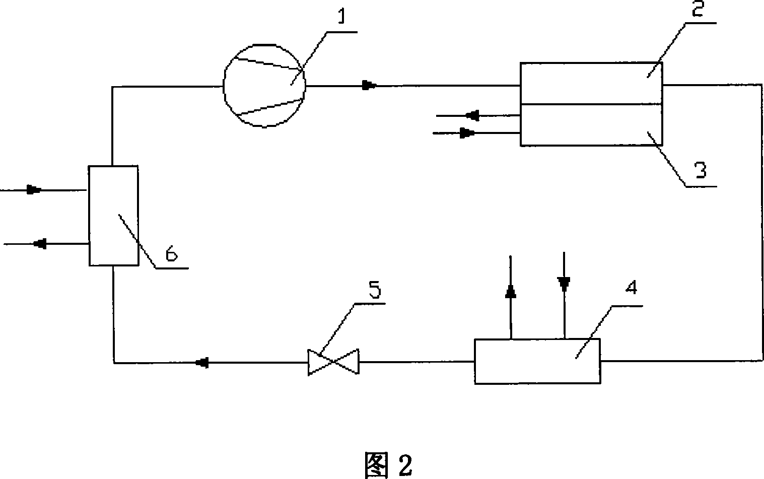
[0016] Shown in accompanying drawing 2 is another embodiment of the heat recovery chiller, which mainly consists of...
PUM
 Abstract
Description
Claims
Application Information
 - Generate Ideas
- Intellectual Property
- Life Sciences
- Materials
- Tech Scout
- Unparalleled Data Quality
- Higher Quality Content
- 60% Fewer Hallucinations
Browse by: Latest US Patents, China's latest patents, Technical Efficacy Thesaurus, Application Domain, Technology Topic, Popular Technical Reports.
© 2025 PatSnap. All rights reserved.Legal|Privacy policy|Modern Slavery Act Transparency Statement|Sitemap|About US| Contact US: help@patsnap.com