
Digital ultrasonic imaging system

An ultrasonic imaging system, digital scan conversion technology, applied in the radio wave measurement system, sound wave re-radiation, utilization of re-radiation, etc., can solve the problems of lack of third-party software support, influence on application promotion, long development cycle, etc., to achieve expansion Operation and diagnosis function, improved resolution, small size effect

Inactive Publication Date: 2007-10-03
易际平
View PDF0 Cites 17 Cited by
  • Summary
  • Abstract
  • Description
  • Claims
  • Application Information

AI Technical Summary

Problems solved by technology

Traditional digital ultrasound imaging systems need to use an integrated amplifier chip and a parallel output A / D conversion chip for each channel or two channels, so a digital ultrasound imaging system with a medium number of channels that meets the requirements of medical diagnosis requires dozens of Amplifiers and A / D chips are combined to form more than one hundred digital signal interfaces, which makes the structure very complex, bulky, high cost, and low reliability, which affects its application and promotion
In addition, in the traditional ultrasound imaging system, the subsequent digital scan conversion, image storage, display, and human-machine interface are usually realized by dedicated circuits. Although the cost is low, its structure is complex, the development cycle is long, and the versatility is very high Poor, lack of third-party software support

Method used


Image

  • Digital ultrasonic imaging system
  • Digital ultrasonic imaging system
  • Digital ultrasonic imaging system

Examples


Embodiment 1

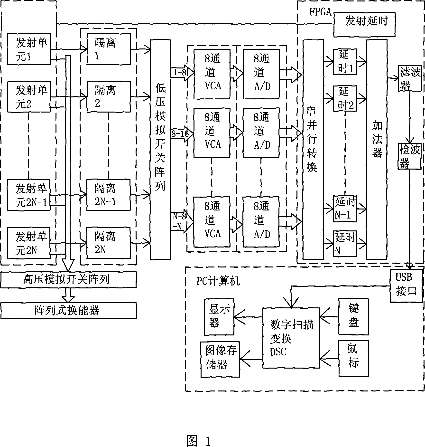
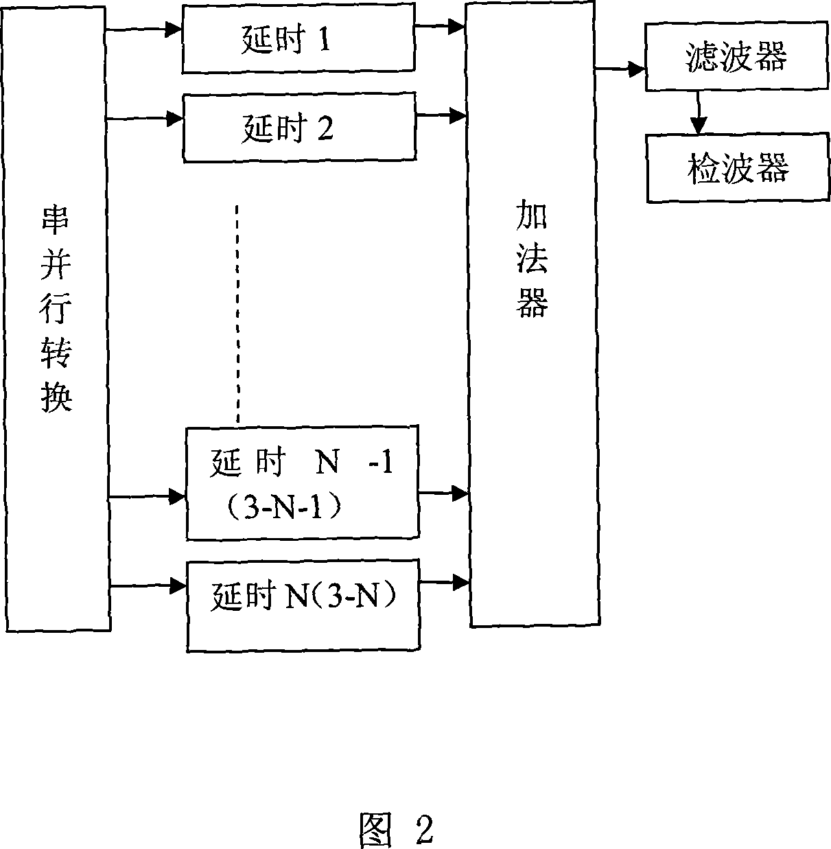
[0026] The block diagram of this embodiment is shown in Figure 1. The digital ultrasonic imaging device includes a group of 2N transmitting units, a group of M high-voltage analog switches, an array probe of M array elements, a group of 2N transceiver isolation units, a A group of 2N×N low-voltage analog switch arrays, a group of (N / 8) 8-way variable gain amplifiers, a group of (N / 8) 8-way serial A / D converters, a transmission delay unit, a USB2.0 interface, a standard PC computer. The PC computer is equipped with a digital scan converter, and also includes a display, an image memory, a keyboard, and a mouse. N is an integer multiple of 8, and N is less than or equal to 128. M is the number of probe array elements. Generally speaking, when M=4N~8N, a more satisfactory image and a lower cost can be obtained.

[0027] A transmit synchronous pulse is delayed by an independent delay transmit channel to generate 2N independent transmit pulses, and after being amplified to a suffi...


PUM


Abstract

The present invention relates to ultrasonic imaging system, and is especially one kind of digital ultrasonic imaging system. The digital ultrasonic imaging system includes a PC with digital scanning converter, a 2N independent delay emitting channel unit, a 64-channel high voltage analog switch array, a 64-element array ultrasonic transducer, a receiving unit, a 2N-input-to-N-output low voltage analog switch array, a N channel variable gain amplifier, a N channel K place A / D converter, and an FPGA module. The present invention has low noise, high gain, high S / N ratio, high resolution and other advantages.

Description

technical field [0001] The invention relates to an ultrasonic imaging system, specifically a digital ultrasonic imaging system. Background technique [0002] The digital ultrasonic imaging system needs to amplify the echo signals received by several or even hundreds of ultrasonic transducers to meet the signal amplitude required by the A / D converter, and form hundreds of thousands of digits after A / D conversion. The signal is then beam-formed. Traditional digital ultrasound imaging systems need to use an integrated amplifier chip and a parallel output A / D conversion chip for each channel or two channels, so a digital ultrasound imaging system with a medium number of channels that meets the requirements of medical diagnosis requires dozens of Amplifiers and A / D chips are combined to form more than one hundred digital signal interfaces, which makes the realized structure very complex, bulky, high in cost and low in reliability, thus affecting its application and popularizatio...

Claims


Application Information

Patent Timeline
IPC IPC(8): G01S15/89
Inventor 易际平
Owner 易际平
Learn More