

Method for preparing CeO2 buffer layer on substrate of metal in cube texture
A cubic texture, metal substrate technology, applied in the direction of metal material coating process, coating, ion implantation plating, etc., can solve the problems of long time, difficult to suppress NiO, low sputtering rate, etc., to ensure integrity , The effect of suppressing the formation of NiO and improving the sputtering efficiency
- Summary
- Abstract
- Description
- Claims
- Application Information
AI Technical Summary
Problems solved by technology
Method used
Image

Examples
preparation example Construction
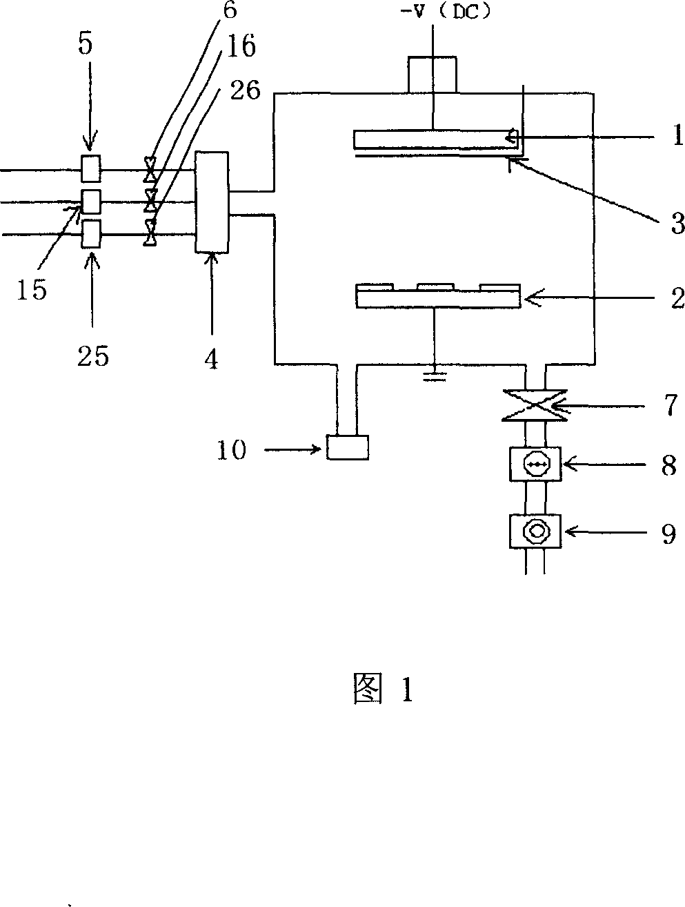
[0027] As shown in Figure 1, the reactive sputtering equipment used in the present invention is in a vacuum chamber, with a sputtering target 1 and a heater 2, the sputtering target 1 and the heater 2 are arranged oppositely, and the sputtering target 1 front is provided with Movable baffle 3; an inlet of sputtering gas is provided on the closed cavity, and the inlet of the sputtering gas is connected to the mixing chamber 4 through the inlet pipeline; the mixing chamber 4 is respectively connected to the argon (Ar) gas inlet pipe Road, H 2 Intake pipeline, O 2 Intake pipeline, and in the argon (Ar) gas intake pipeline, H 2 Intake pipeline, O 2 Mass flowmeters 5, 15, 25, and stop valves 6, 16, 26 are respectively installed on the air intake pipeline; a vacuum pipeline interface is provided on the closed cavity, and the vacuum pipeline interface is connected to the vacuum pipeline, and the ram is connected in series on the vacuum pipeline. valve 7, molecular pump 8, mechanic...
Embodiment 1
[0038] Preparation of CeO by Reactive Sputtering 2 For the buffer layer, the target material is a Φ64×4mm pure metal Ce (99.9%) target, and the distance between the target and the base is about 30mm.
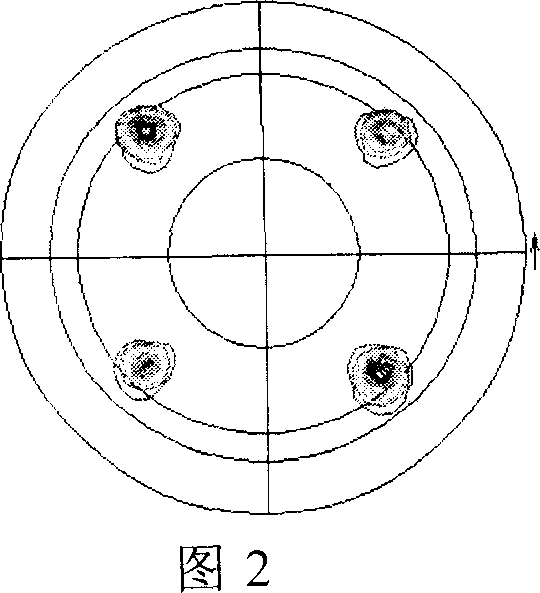
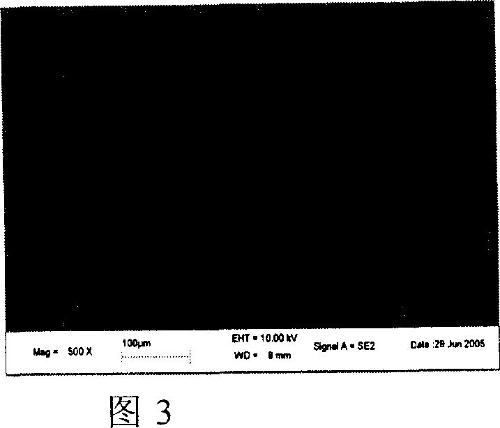
[0039] Cut the Ni metal strip with a cubic texture (the (111) pole figure of the Ni baseband is shown in Figure 2, and the scanning electron microscope image is shown in Figure 3), and cut it into a sample with a size of 3mm×10mm, and put it in alcohol Ultrasonic cleaning was performed for 2 minutes, followed by ultrasonic cleaning in acetone for 3 minutes.
[0040] Put the prepared Ni base tape on the heater of the equipment (the equipment is shown in Figure 1), and vacuumize to 1×10 -2 Pa, followed by Ar / H 2 (60 / 10) mixed gas, adjust the air pressure to 13Pa, raise the heater temperature to 650°C within 5 to 10 minutes, balance for about 5 minutes, turn on the sputtering power, slowly increase the sputtering power to 80W, and balance After about 10 minutes, remove the baffl...
Embodiment 2
[0045] Preparation of CeO by Reactive Sputtering 2 For the buffer layer, the target material is a Φ64×4mm pure metal Ce (99.9%) target, and the distance between the target and the base is about 30mm.
[0046] Cut the Ni metal strip with a cubic texture (the (111) pole figure of the Ni baseband is shown in Figure 2, and the scanning electron microscope image is shown in Figure 3), and cut it into a sample with a size of 10mm×10mm, and put it in alcohol Ultrasonic cleaning was performed for 2 minutes, followed by ultrasonic cleaning in acetone for 3 minutes.
[0047] Put the prepared Ni base tape on the heater of the device (the device is shown in Figure 1), and then evacuate to 1×10 -2 Pa, followed by Ar / H 2 (60 / 10) mixed gas, and adjust the air pressure to 26Pa, raise the heater temperature to 680°C within 5 to 10 minutes, balance for about 5 minutes, turn on the sputtering, slowly increase the sputtering power to 80W, and balance for about After 10 minutes, remove the baff...
PUM
| Property | Measurement | Unit |
|---|---|---|
| lattice constant | aaaaa | aaaaa |
| purity | aaaaa | aaaaa |
Abstract
Description
Claims
Application Information