Changeable outlet flow section turbine jet nozzle ring

A turbine nozzle and deflector technology, applied in combustion engines, machines/engines, internal combustion piston engines, etc., can solve the problems of large volume, complex structure and high price

Inactive Publication Date: 2007-10-10
孙敏超
View PDF0 Cites 15 Cited by
  • Summary
  • Abstract
  • Description
  • Claims
  • Application Information

AI Technical Summary

Problems solved by technology

Disadvantages are: complex structure, high manufacturing precision, high price, large volume; working at high temperature for a long time, it is difficult to ensure the reliability of the structure and operating system, so it is only used in turbochargers of diesel engines with relatively low gas temperature So far, it has not been widely used in turbochargers for gasoline engines with higher gas temperature; the high-temp

Method used


Image

  • Changeable outlet flow section turbine jet nozzle ring
  • Changeable outlet flow section turbine jet nozzle ring
  • Changeable outlet flow section turbine jet nozzle ring

Examples


Example Embodiment

[0053] Hereinafter, the technical content of the present invention will be further described through embodiments and in conjunction with the accompanying drawings.

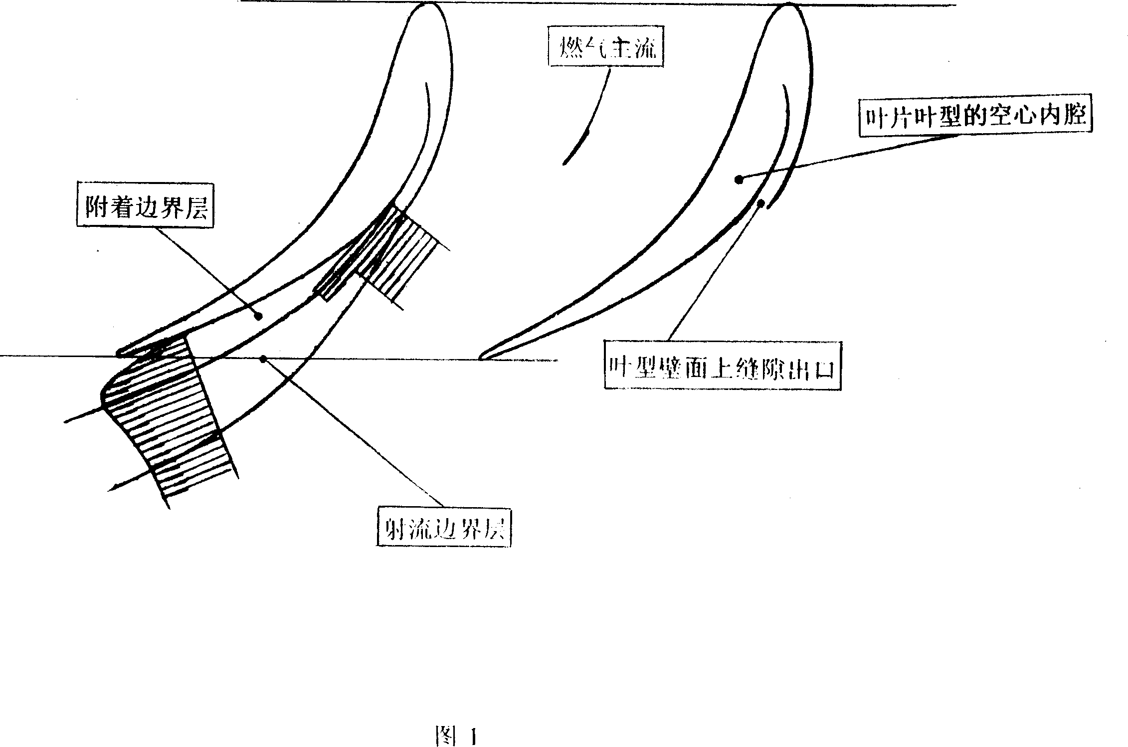
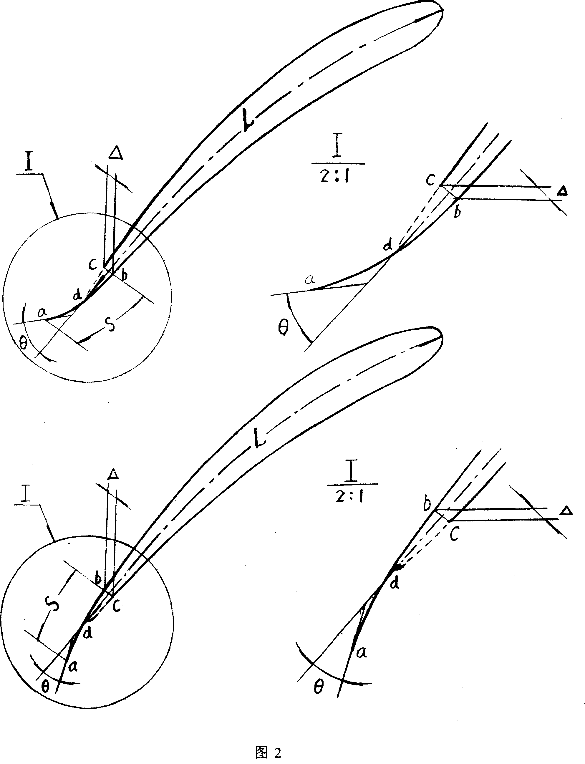
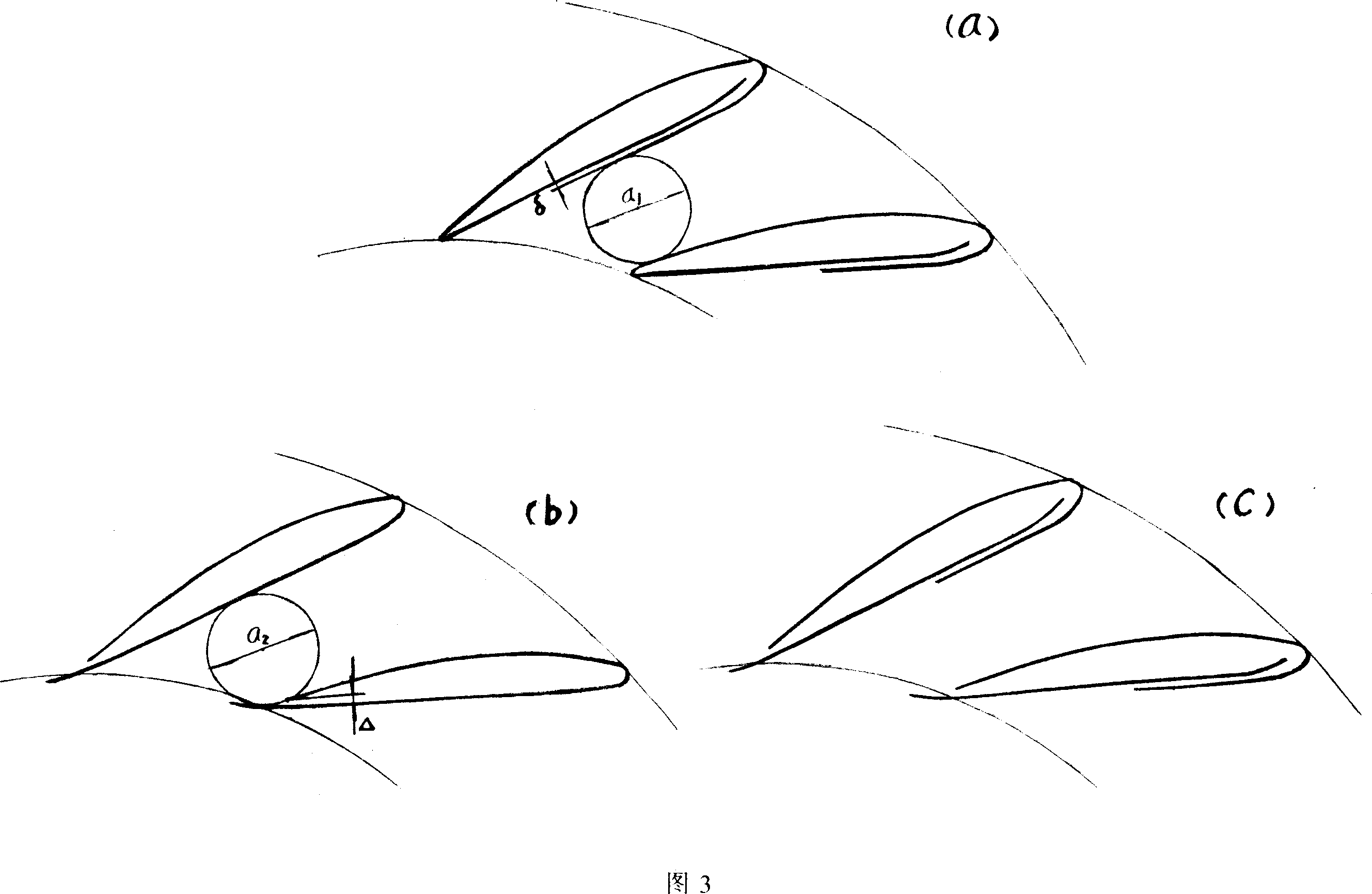
[0054] As mentioned above, the technical core of the present invention is the use of external compressed air to pass through the hollow cavity of the nozzle blade, through the flow slot cut by the airfoil profile and / or the trailing edge (the trailing edge slot is attached with The arc-shaped baffle) blows the main flow of gas in the nozzle ring cascade flow channel and / or the cascade outlet downstream, so that the air flow mixed with the slit jet and the main flow will deflect at the nozzle ring outlet in a direction different from the original main flow direction, causing The change of outlet airflow angle (ie, outlet flow cross-sectional area). Through the pressure regulating valve to regulate the supply pressure of the compressed air, the outlet airflow angle will be changed as required to meet the demand for boos...


PUM


Abstract

The present invention belongs to the field of internal combustion engine turbocharging technology, in particular, it relates to a turbine nozzle ring used in turbocharger. Said invention provides the working principle of said turbine nozzle ring, and also provides the concrete structure of said turbine nozzle ring and its manufacture method.

Description

Technical field [0001] The invention relates to a turbine nozzle ring in a turbocharger in the technical field of turbocharging of an internal combustion engine. Background technique [0002] The use of variable nozzle turbo regulation technology for turbochargers is an effective measure developed in the past two decades to improve the torque reserve and transient response of internal combustion engines, and to reduce fuel consumption and harmful emissions. By changing the flow cross-sectional area of ​​the outlet of the turbine nozzle ring vane, a good match between the turbocharger and the internal combustion engine can be achieved in the full range of operating conditions. [0003] The existing technology of variable nozzle turbine adjustment, without exception, adopts the technical solution of adjustable nozzle. Adjustable nozzles use mechanical means to rotate the nozzle blades (change the installation angle of the nozzle blades in the turbine nozzle ring cascade) to change ...

Claims


Application Information

Patent Timeline
IPC IPC(8): F02B37/24
CPCY02T10/144Y02T10/12
Inventor 孙敏超孙正柱
Owner 孙敏超
Why Eureka
Try Eureka