Liquid crystal display devices and polarizing plate sets used therein

A technology of liquid crystal display devices and polarizers, applied in polarizing elements, optics, instruments, etc., can solve the problems of brightness leakage, large color shift, etc., and achieve the effects of reducing the number of used parts, eliminating edge irregularities, and reducing the number of processes

Inactive Publication Date: 2007-10-10
SUMITOMO CHEM CO LTD
View PDF7 Cites 10 Cited by
  • Summary
  • Abstract
  • Description
  • Claims
  • Application Information

AI Technical Summary

Problems solved by technology

However, sometimes in the black display state, the brightness leakage caused by the viewing angle can still be observed, and there are problems such as large color shift caused by the viewing angle.

Method used


Image

  • Liquid crystal display devices and polarizing plate sets used therein
  • Liquid crystal display devices and polarizing plate sets used therein
  • Liquid crystal display devices and polarizing plate sets used therein

Examples


Embodiment 1

[0091] (a) The first polarizer

[0092] A linear polarizing plate was prepared, which was one side of a polarizer in which iodine was adsorbed and oriented on a polyvinyl alcohol film, and a non-oriented transparent protective film (manufactured by Fuji Film Co., Ltd. Z-TAC”, R 0 =2nm, Rth=0nm), on the other side, a transparent protective film made of cellulose triacetate was attached. Use it as the first polarizer.

[0093] (b) Second polarizer

[0094] The norbornanyl resin film was oriented in the thickness direction according to the method described in the above-mentioned patent document 6, and R 0 =280 nm, three-dimensionally oriented transparent resin film of Nz=0.4. When the wavelength dispersion of the retardation of the obtained transparent resin film is measured, it is

[0095] R(450nm) / R(550nm)=1.00,

[0096] R(650nm) / R(550nm)=1.00.

[0097] The measurement wavelengths are indicated in parentheses.

[0098] The above-mentioned three-dimensionally oriented tr...

Embodiment 2

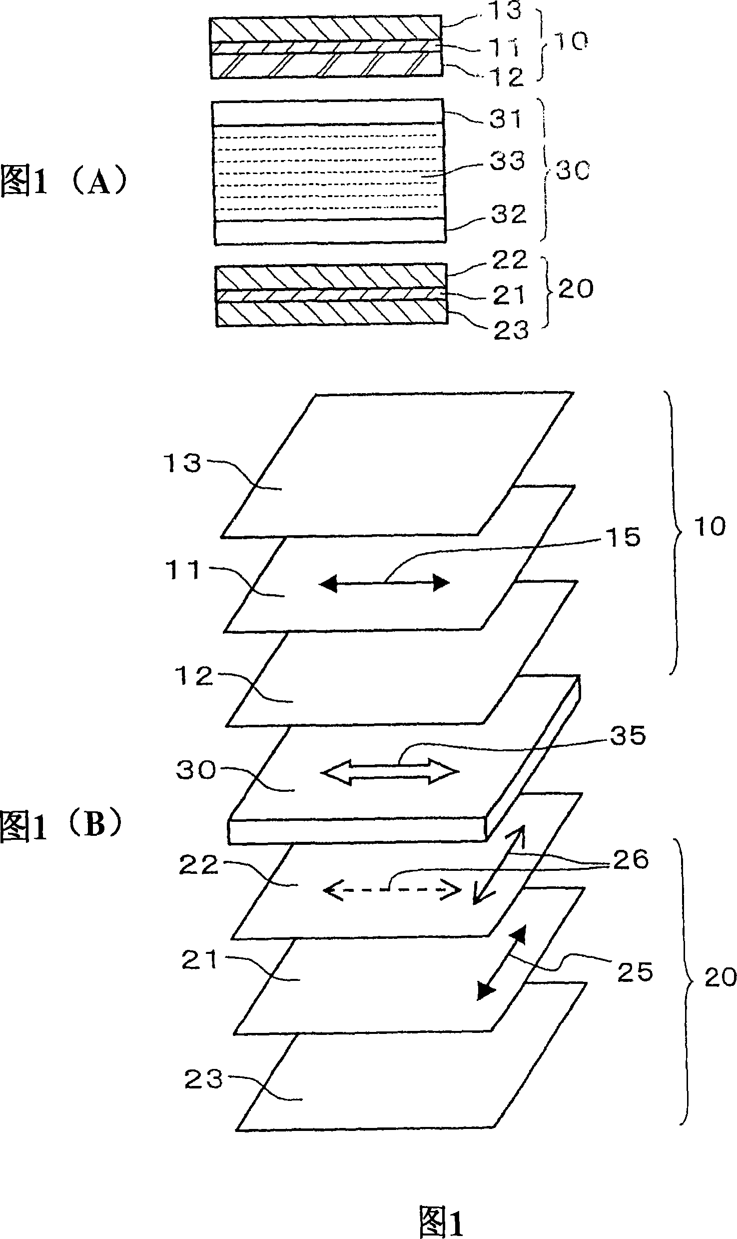
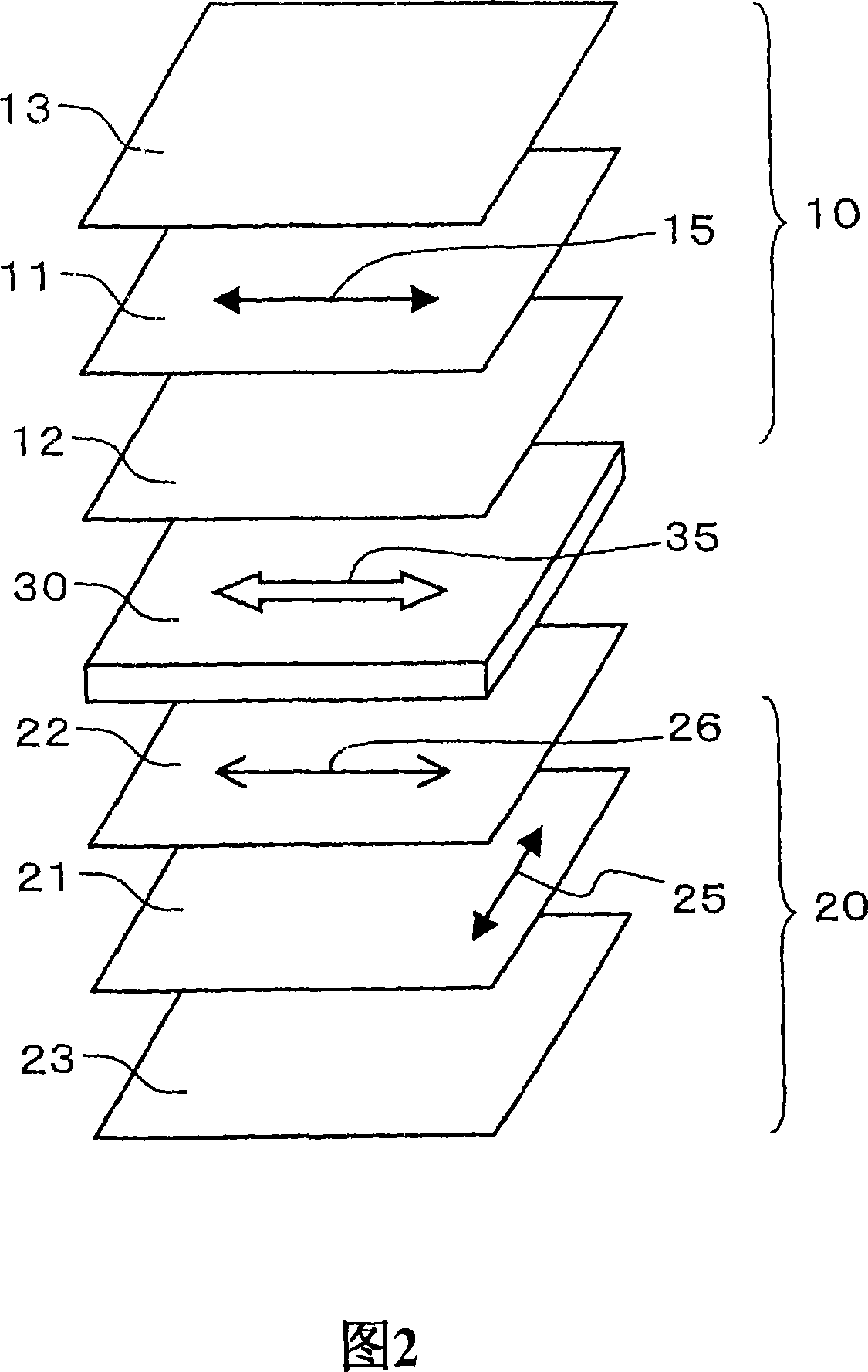
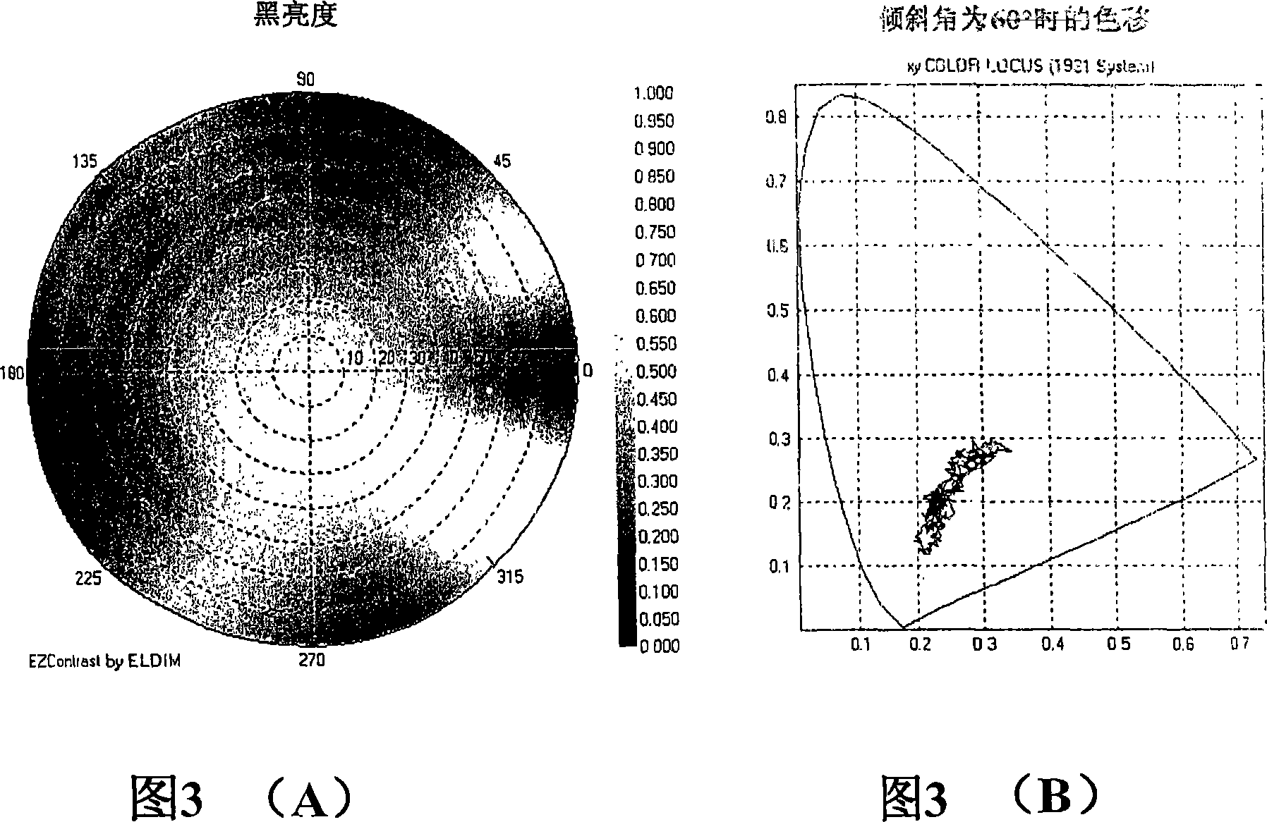
[0105] A liquid crystal display device was produced and evaluated in the same manner as in Example 1, except that the retardation axis of the three-dimensionally oriented resin film constituting the second polarizing plate was parallel to the absorption axis of the polyvinyl alcohol iodine polarizer. The layer configuration and axis relationship of the liquid crystal display device manufactured here are shown in a schematic perspective view in FIG. 4 . In the arrangement shown in this figure, the retardation axis 26 of the transparent protective layer 22 on the side of the liquid crystal cell constituting the second polarizing plate 20 is fixed in a direction parallel to the absorption axis 25 of the polarizer 21. Only this point is different from that of FIG. 1(B )different. The evaluation results of this example are shown in FIG. 5 in the same manner as in FIG. 3 . However, FIG. 5(A) shows a place where the inclination angle is close to 90° from the normal direction. From ...

Embodiment 3

[0107] (a) The first polarizer

[0108] A linear polarizing plate was prepared as a first polarizing plate in the same manner as in (a) of Example 1.

[0109] (b) Second polarizer

[0110] The norbornanyl resin film was oriented in the thickness direction according to the method described in the above-mentioned patent document 6, and R 0 =250nm, three-dimensionally oriented transparent resin film of Nz=0.4. The wavelength dispersion of the retardation of the obtained transparent resin film was as good as that obtained in (b) of Example 1. The measurement wavelengths are indicated in parentheses.

[0111] Using a polyvinyl alcohol-based adhesive, the above three-dimensionally oriented transparent resin film is attached to one side of a polarizer in which the polyvinyl alcohol film is adsorbed and oriented with iodine, and a transparent protective film containing cellulose triacetate is attached to the other side. , to manufacture linear polarizers. At this time, the in-pla...


PUM


Abstract

The present invention provides a IPS mode liquid crystal display device and polarizing plate set used therein, the device can improves the leakage of black brightness when side glancing, and the color migration is little caused by angle of visibility. The liquid crystal unit (30) has two pieces of base plates (31, 32) between liquid crystal layers (33) in parallel with the base plate approximately and sealed with the base plate. A pair of polarizing plates (10, 20) clamping the liquid crystal unit (30) are arranged as absorbing axles (15, 25) orthometric with the both. The base side transparent protection layer of the first polarizing plates (10) is set to be film less than 10nm in plane phase separation R<0> (1), and less than 20nm in thickness direction phase separation R<2> (2). The base side transparent protection layer of the second polarizing plates (20) is set to be film 200-300nm in plane phase separation R<0> (2), and 0.4-066 in Nz coefficient [=(n-n) / (n-n)]. In the second polarizing plates (20), the delay axle (22) of the base side transparent protection layer (20), and the absorbing axle (25) of the polarizer are in parallel or orthogonality.

Description

technical field [0001] The present invention relates to a wide viewing angle liquid crystal display device that can be used as a transverse electric field (in-panel switching: IPS) mode. The present invention also relates to a polarizer combination used in the liquid crystal display device. Background technique [0002] In recent years, due to various advantages such as low power consumption, low-voltage operation, light weight, and thin shape, liquid crystal display devices (LCD) have been used as information devices such as mobile phones, portable information terminals (Personal Digital Assistants: PDA), personal computers, and televisions. The use of display devices is rapidly increasing. With the development of LCD technology, various modes of LCDs have been proposed, which are gradually solving the problems of LCD response speed, contrast ratio, and narrow viewing angle. In addition, the viewing angle can be further improved by sandwiching a retardation plate between ...

Claims


Application Information

Patent Timeline
Patent Type & Authority Applications(China)
IPC IPC(8): G02F1/1335G02B5/30
CPCG02B5/3033G02B5/3083G02F1/133528G02F1/133634G02F1/134363
Inventor 角谷英则金奉春
Owner SUMITOMO CHEM CO LTD
Why Eureka
Try Eureka