
Electromagnetic compatible shield device and measuring method for electromagnetic shield effect

A shielding device and electromagnetic compatibility technology, which is applied in the fields of magnetic/electric field shielding, measuring devices, and electromagnetic field characteristics, can solve problems such as poor high-frequency characteristics, complicated electromagnetic compatibility test methods, and restrictions on the application range and test effect of electromagnetic shielding effect tests. , to achieve the effect of reasonable structure, easy implementation and simple structure

Inactive Publication Date: 2007-10-10
苏州沃野系统控制技术有限公司
View PDF0 Cites 11 Cited by
  • Summary
  • Abstract
  • Description
  • Claims
  • Application Information

AI Technical Summary

Problems solved by technology

However, the existing electromagnetic compatibility shielding devices usually only use ordinary metal materials to make a fully enclosed cavity, which has a general electromagnetic shielding function.
Because the structure of this device is very simple, it can only be applied to low-frequency electromagnetic shielding, and cannot effectively shield high-frequency or ultra-high-frequency electromagnetic
The electromagnetic shielding effect test is based on the electromagnetic compatibility shielding device with high conductivity and high Q performance, that is, it is based on the theoretically closed and uniform field strength test space. The frequency characteristics are very poor, and the calculation of the uniform field of the wave mode reverberation chamber and the electromagnetic compatibility test method based on statistics are very complicated, which seriously restricts the application range and test effect of the electromagnetic shielding effect test.

Method used


Image

  • Electromagnetic compatible shield device and measuring method for electromagnetic shield effect
  • Electromagnetic compatible shield device and measuring method for electromagnetic shield effect

Examples


Embodiment Construction

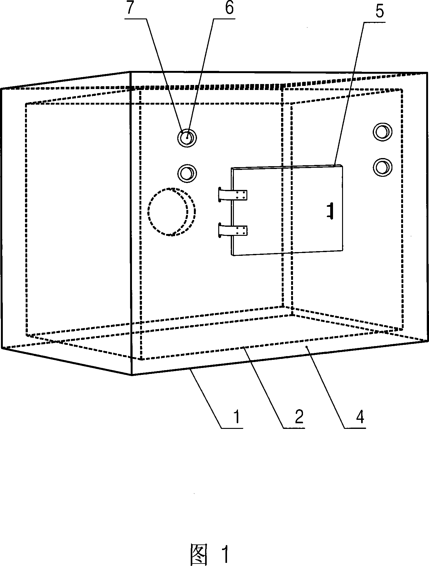
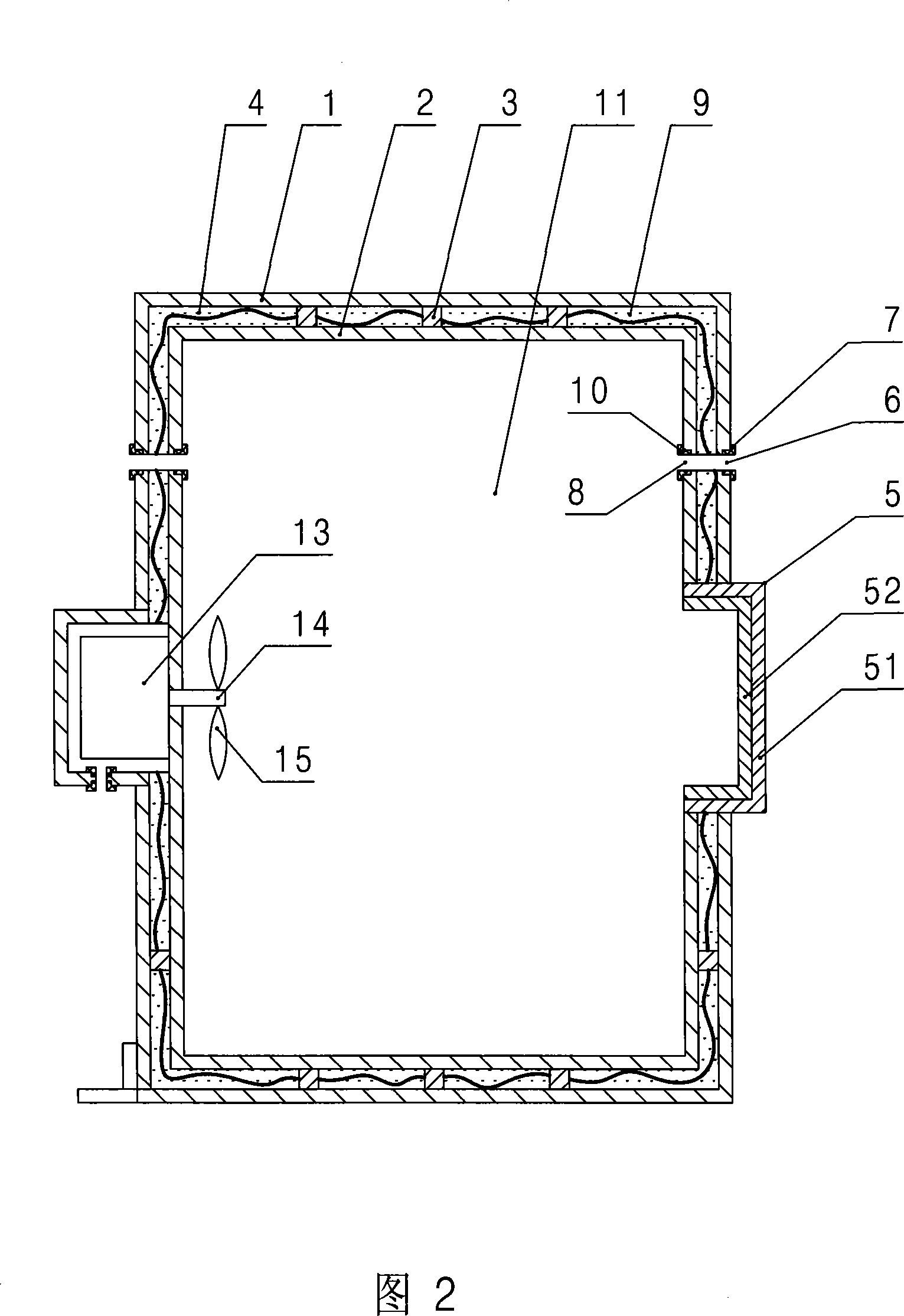
[0032] As shown in Fig. 1 and Fig. 2, the electromagnetic compatibility shielding device according to the present invention includes a closed shell 1 made of high-conductivity material, and a closed metal liner 2 is arranged inside the closed shell 1, The metal liner 2 is made of electromagnetic wave reflective material, the outer shell 1 and the inner liner 2 are fixedly connected to each other through several brackets 3, and a partition 4 is formed between them, and a hatch 5 is arranged on the outer shell 1 and the inner liner 2 The material of the inner and outer layers of the hatch door 5 is consistent with the electromagnetic properties of the material of the outer shell 1 and the inner tank 2 respectively, the outer layer 51 of the hatch door is sealed and connected with the outer shell 1, and the inner layer 52 of the hatch door is enclosed with the inner tank 2 to form a sealed Inner cavity 11; the shell 1 and the inner liner 2 are respectively provided with through ho...


PUM

PropertyMeasurementUnit
electrical bandwidthaaaaaaaaaa

Abstract

The invention uses a bilayer structure; in which, the outer layer is made of a kind of materials that has high conductance and high absorption of electromagnet wave; the inner layer is made of a high reflection and low absorption. The method comprises: setting the sweeping frequency and dotting frequency; starting the wave mode agitator; transmitting the dotting frequency in stepping, respectively sampling the signals of dotting frequency from antenna and detecting ware; counting and analyzing the signals to decide if it fits the character of uniform field; making the dotting frequency process and sweeping frequency synthesis; saving them; making count and analyzes for the sweep data from the antenna the detection ware; figuring out the electromagnet shield effect.

Description

technical field [0001] The invention relates to an electromagnetic compatibility testing device and a method for testing electromagnetic shielding effect by using the device. Background technique [0002] Electromagnetic compatibility testing is related to ensuring information security and reducing electromagnetic pollution, and the application of its testing devices, technologies and methods is becoming more and more important. Electromagnetic shielding effect test is an important part of electromagnetic compatibility test. The electromagnetic shielding effect test is inseparable from the electromagnetic shielding test system, which usually includes: an electromagnetic compatibility shielding device, a transmitting antenna, a receiving antenna and a detection part arranged in the electromagnetic compatibility shielding device, as well as a microwave signal generator for generating signals, A spot frequency signal sampler for sampling and a computer or embedded system for c...

Claims


Application Information

Patent Timeline
Patent Type & Authority Applications(China)
IPC IPC(8): H05K9/00G01R29/08G01R29/10G01R31/00G01N23/00
Inventor 邱宏杰康南生柏立洲
Owner 苏州沃野系统控制技术有限公司
Learn More