Stereomicroscope side-irradiation type lighting method and its dark view stereomicroscope

A technology of stereo microscope and lighting method, which is applied in the direction of microscope, optics, instrument, etc. It can solve the problems of not being able to distinguish the subtleties of specimens, the reduction of imaging signal-to-noise ratio, and the increase of background light, so as to improve the brightness and clarity, improve contrast and signal-to-noise ratio, and overcome the effect of insufficient lighting

Inactive Publication Date: 2007-10-17
TONGJI HOSPITAL ATTACHED TO TONGJI MEDICAL COLLEGE HUAZHONG SCI TECH
View PDF0 Cites 17 Cited by
  • Summary
  • Abstract
  • Description
  • Claims
  • Application Information

AI Technical Summary

Problems solved by technology

Its shortcoming is that there is a vertical interfering light 4 at the same time, and after the interfering light 4 vertically irradiates a certain point 5 on the stage 10 on the periphery of the specimen 2, a vertical reflected light 6 returning from the original path is formed, and the vertical reflected light 6 finally Also enters the objective lens and interferes with the observed specimen 2
However, since the illumination light is irradiated obliquely from below, the illumination on the surface above the specimen is severely insufficient and the contrast is low, and it is difficult to distinguish the subtleties on the surface above the specimen. Therefore, it is necessary to combine epi-illumination to eliminate the insufficient illumination above the specimen. part, but the result also leads to the increase of the background light, which reduces the signal-to-noise ratio of the imaging

Method used


Image

  • Stereomicroscope side-irradiation type lighting method and its dark view stereomicroscope
  • Stereomicroscope side-irradiation type lighting method and its dark view stereomicroscope
  • Stereomicroscope side-irradiation type lighting method and its dark view stereomicroscope

Examples


Embodiment Construction

[0024] Below in conjunction with accompanying drawing and specific embodiment the present invention is described in further detail:

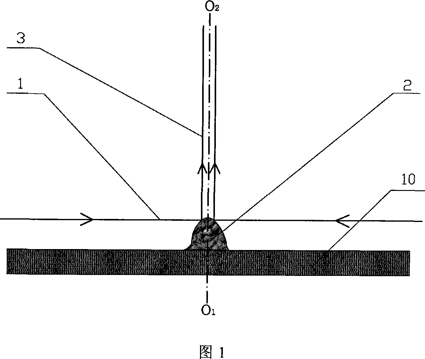
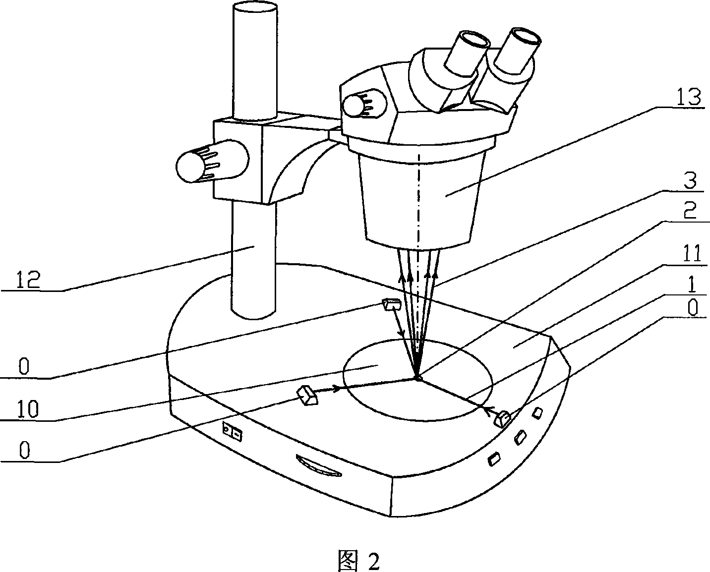
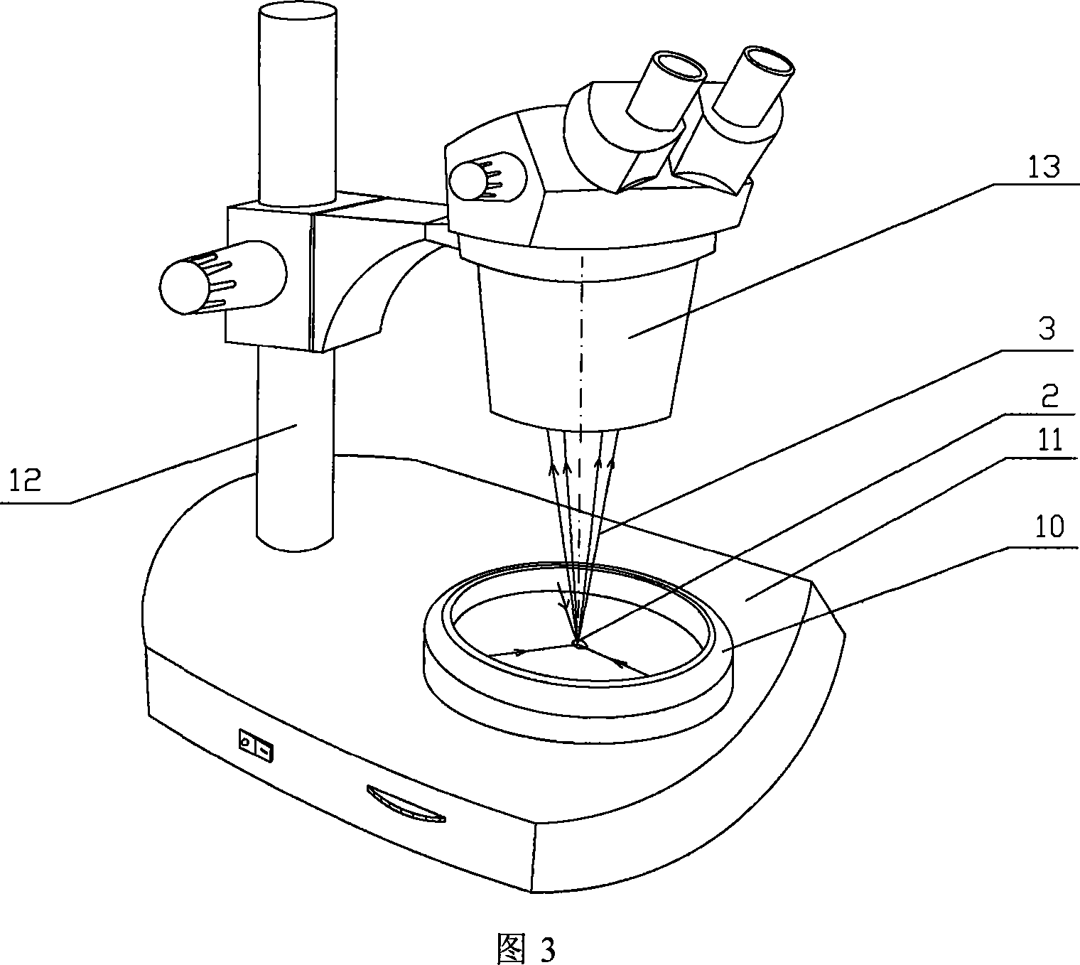
[0025] As shown in Figure 1, it is the schematic diagram of the optical path principle of the stereomicroscope side illumination type illumination method of the present invention, the light beam 1 that the light source sends among the figure irradiates the observed specimen 2 from the side of the stereomicroscope stage 10, and the light beam 1 can be The last light part of the effective illumination directly emitted by the light source, or the last light part of the effective illumination formed by the light source after passing through a series of optical instruments and changing directions. The beam 1 and the specimen 2 are in the same plane space range, the symmetry line O between the beam 1 and the main optical axes of the two objective lenses of the stereo microscope 1 o 2 Vertical, but a deviation of ±10° is allowed. After the light beam...


PUM


Abstract

The invention relates to a stereomicroscope side lighting method and the dark-field stereomicroscope thereof. The method uses the beam emitted from the light source to lighting the observed sample from the side of the stereomicroscope stage, and the beam is satisfied the following characteristic: firstly,the beam and the observed sample are in a same plane spatial limit, secondly, the included angle between the beam and the symmetrical line O1O2 of the two object lens primary optic axis of the stereomicroscope is 80 to 100 degrees. The design consideration of the dark-field stereomicroscope which is an improvement for the traditional stereomicroscope, is enable the last light part directly emitted from the light source or through the optical instrument to change the direction to horizontally locate the observed sample stage, so that the symmetrical line O1O2 of the stage and the two object lens primary optic axis is arranged vertically. By using the method and the dark-field stereomicroscope thereof can effectively lighten the interference of the background light, greatly improve the contrast and the signal to noise ratio of the observed sample, especially fit for the liquid phase dissection observation.

Description

technical field [0001] The invention relates to an improved design of a stereo microscope illumination method in the technical field of medical microdissection, in particular to a side illumination illumination method of a stereo microscope and a dark field stereo microscope thereof. Background technique [0002] Stereo microscopes, also known as dissecting microscopes, are widely used in medical research and other fields. The special observation effect of a stereo microscope depends on the effective lighting method. Conventional stereo microscope lighting methods can be divided into epi-illumination methods and transmissive lighting methods according to the formation of their illumination beams. [0003] The epi-illumination method is also called the reflective lighting method, which is mainly suitable for non-transparent specimens to be inspected, and its illumination source comes from above the specimens to be inspected. Epi-illumination metho...

Claims


Application Information

Patent Timeline
Patent Type & Authority Applications(China)
IPC IPC(8): G02B21/06G02B21/24G02B21/26
Inventor 周良强褚汉启倪坤
Owner TONGJI HOSPITAL ATTACHED TO TONGJI MEDICAL COLLEGE HUAZHONG SCI TECH
Why Eureka
Try Eureka