Tension mechanism adapted for automatic optical fiber winding machine

A technology of optical fiber winding machine and tension mechanism, which is applied in the direction of light guide, optics, optical components, etc., can solve the problems of unguaranteed winding quality, low precision of tension control, unstable transmission control, etc., and achieve no reverse dead zone, Improved tension control accuracy and strong dimensional changes

Inactive Publication Date: 2007-10-24
BEIHANG UNIV
View PDF0 Cites 16 Cited by
  • Summary
  • Abstract
  • Description
  • Claims
  • Application Information

AI Technical Summary

Problems solved by technology

How to wind a high-quality fiber optic ring is very important to the development of fiber optic gyroscopes. There are many winding methods, and the quadrupole symmetrical winding method has the best effect, which is a method commonly used in the world. Manual winding is adopted, and there is no special equipment, so the winding quality cannot be guaranteed
[0004] At present, the tension mechanism used in some automatic optical fiber winding machines has defects such as simple structure, no backlash elimination mechanism, unstable transmission control, low tension control precision, and zero point drift.

Method used


Image

  • Tension mechanism adapted for automatic optical fiber winding machine
  • Tension mechanism adapted for automatic optical fiber winding machine
  • Tension mechanism adapted for automatic optical fiber winding machine

Examples


Embodiment Construction

[0029] The present invention will be further described in detail below in conjunction with the accompanying drawings.

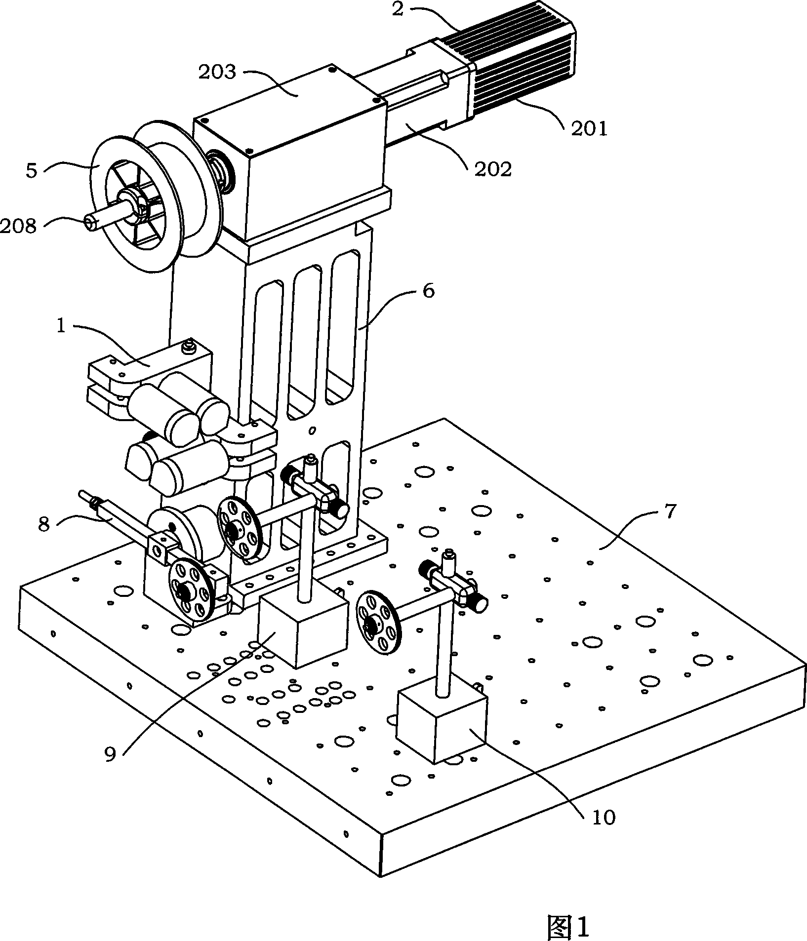
[0030] Referring to Fig. 1, the present invention is a tension mechanism applicable to an automatic optical fiber winding machine. Table 7 tension assembly 8, the first fiber guide assembly 9 and the second fiber guide assembly 10, the lower end of the support base 6 is installed on the slide table 7 through screws and nuts; the upper end of the support base 6 is equipped with a transmission box 4; the drive assembly 2 is installed on the transmission box body 4, and the motor 201 and the reducer 202 are placed on the outer rear side of the transmission box body 4, and the precision main shaft 208 of the drive assembly 2 is suspended on the outer front side of the transmission box body 4; the precision main shaft of the drive assembly 2 208 is installed with a fiber payout wheel 5; the optical fiber convergence assembly 1 is installed on one side of the suppo...


PUM


Abstract

The invention discloses a tension structure used in automatic fiber coiler, composed of a fiber collector, a driver, a transmit box, a fiber discharge wheel, a support base, and a sliding table tension element, a first fiber guider and a second fiber guider, wherein the lower end of the support base via nut and screw is mounted on the sliding table, while the upper end is mounted with the transmit box, the driver is on the transmit box, while a motor and a speed reducer are mounted at the outer back of the transmit box, the accurate shaft of the driver is suspended at the outer front of the transmit box, which is mounted with the fiber discharge wheel, the fiber collector is at one side of the support base, vertically with the fiber discharge wheel, the sliding table is arranged with a plurality of mounting holes for fixing and mounting devices, the tension element, the first and the second fiber guiders via nut and screw are fixed on the sliding table, which guide grooves are in one plane. The inventive tension device has reasonable, compact and simple structure, without reverse dead area, but with stable transmission control, accurate tension control, non-zero-bias in force measurement, digit and closed tension control.

Description

technical field [0001] The invention relates to a tension mechanism suitable for an automatic optical fiber looping machine. Background technique [0002] The fiber optic gyroscope was born in 1976. It is a new type of sensor that uses fiber optic sensing technology to measure the space inertial rotation rate. It has developed into a new mainstream instrument with epoch-making characteristics in the field of inertial technology. Compared with the laser gyroscope, it has higher precision, low cost, small size and light weight. The application prospect of fiber optic gyroscope is very broad. It is not only used for aircraft and ship navigation, missile guidance, and high-precision position control of spacecraft, but also can be used for civilian use in the guidance of high-end cars, as well as robots and automatic control systems, etc. . [0003] The fiber optic ring is the sensing core of the fiber optic gyroscope, and its basic requirements are a large extinction ratio and...

Claims


Application Information

Patent Timeline
Patent Type & Authority Applications(China)
IPC IPC(8): G02B6/00B65H59/10G01C19/72
Inventor 董全林张春熹邵洪峰姜长星韩敏
Owner BEIHANG UNIV
Why Eureka
Try Eureka