

A system and method for realizing the isolation of high frequency switch DC-DC conversion
A high-frequency switching, DC-DC technology, applied in conversion equipment with intermediate conversion to AC, control/regulation systems, conversion of DC power input to DC power output, etc., can solve the risk of low dynamic adjustment response and transformer magnetic saturation , isolation transformer whistling and other problems, to achieve the effect of improving dynamic adjustment response speed, avoiding delay, and high dynamic adjustment response capability
- Summary
- Abstract
- Description
- Claims
- Application Information
AI Technical Summary
Problems solved by technology
Method used
Image

Examples
Embodiment 1
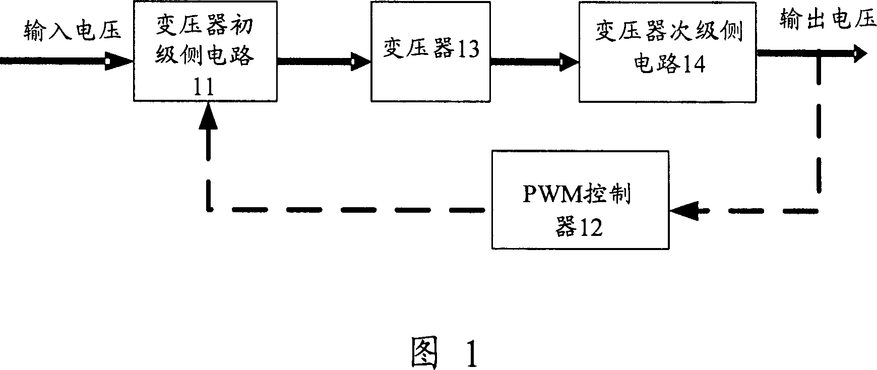
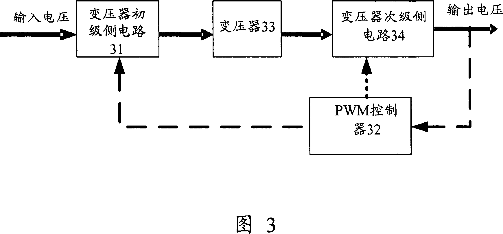
[0059] FIG. 4 is a schematic structural diagram of a system implementing DC-DC conversion of an isolated high-frequency switch according to Embodiment 1 of the present invention. Referring to FIG. 4 , the system includes: a transformer primary side circuit 31 , a PWM controller 32 , a transformer 33 and a transformer secondary side circuit 34 . in,
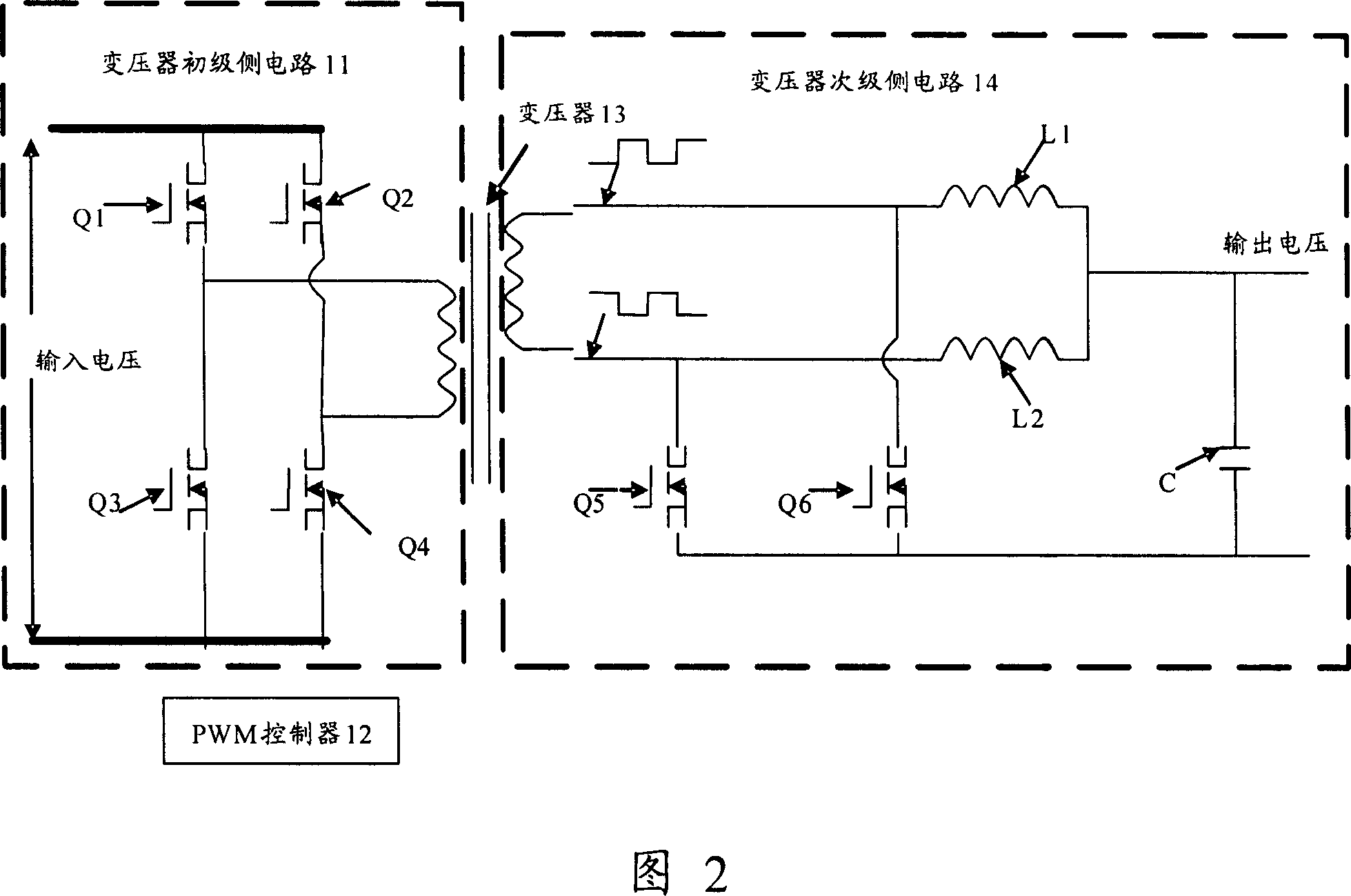
[0060] The transformer primary side circuit 31 includes MOS transistors Q1, Q2, Q3 and Q4, the source of MOS transistor Q1 is connected to the drain of MOS transistor Q3 and the input voltage of the transformer, the source of MOS transistor Q2 is connected to the drain of MOS transistor Q4 and the input voltage of the transformer The other ends are connected; the drains of MOS transistors Q1 and Q2 are connected to one end of the input voltage, the sources of MOS transistors Q3 and Q4 are connected to the other end of the input voltage, and the MOS transistors Q1, Q3, Q2, and Q4 respectively form the primary side of the isolated D...
Embodiment 2
[0090] In the first embodiment, in the conversion circuit topology circuit having the combined functions of two-phase BUCK conversion and synchronous rectification, the two-phase BUCK conversion circuit constitutes a single output voltage conversion circuit. It is also possible to independently output each phase of the two-phase BUCK conversion circuits to form a dual-output voltage conversion circuit.
[0091] FIG. 12 is a schematic structural diagram of a system implementing DC-DC conversion of an isolated high-frequency switch according to Embodiment 2 of the present invention. Referring to FIG. 12 , the system includes: a transformer primary side circuit 31 , a PWM controller 32 , a transformer 33 and a transformer secondary side circuit 34 . in,
[0092] Transformer primary side circuit 31, including MOS transistors Q1, Q2, Q3 and Q4, forms two bridge arms of the primary side full bridge of the isolated DC-DC conversion transformer, and is used for full bridge conversion...
Embodiment 3
[0111] FIG. 15 is a schematic structural diagram of a system implementing DC-DC conversion of an isolated high-frequency switch according to Embodiment 3 of the present invention. Referring to FIG. 15 , it includes a transformer primary side circuit 31 , a transformer 33 , an intermediate voltage conversion circuit, a PWM controller 32 and a post-stage non-isolated DC-DC conversion circuit.
[0112] Transformer primary side circuit 31, including MOS transistors Q1, Q2, Q3 and Q4, forms two bridge arms of the primary side full bridge of the isolated DC-DC conversion transformer, and is used for full bridge conversion of the input voltage;
[0113] Transformer 33 is an isolated main transformer with a center tap, and the center tap is used as the third output terminal of the transformer; it is used for isolating the primary side circuit of the transformer and the intermediate voltage conversion circuit and converting the input voltage of the transformer into the output voltage of...
PUM
 Abstract
Description
Claims
Application Information