Florescent lamp, light-storage florescent lamp, illuminating device and light-storage illuminating device

A light-emitting device and fluorescent lamp technology, applied in the direction of luminescent materials, parts of gas discharge lamps, chemical instruments and methods, etc., can solve problems such as poor color rendering, narrow color gamut, and low brightness

Inactive Publication Date: 2007-10-31
黎涤萍
View PDF0 Cites 21 Cited by
  • Summary
  • Abstract
  • Description
  • Claims
  • Application Information

AI Technical Summary

Problems solved by technology

However, compared with ordinary fluorescent lamps and light-emitting devices, existing phosphorescent fluorescent l

Method used


Image

  • Florescent lamp, light-storage florescent lamp, illuminating device and light-storage illuminating device
  • Florescent lamp, light-storage florescent lamp, illuminating device and light-storage illuminating device
  • Florescent lamp, light-storage florescent lamp, illuminating device and light-storage illuminating device

Examples


Embodiment 1

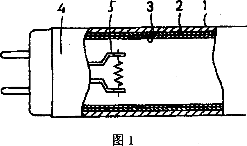
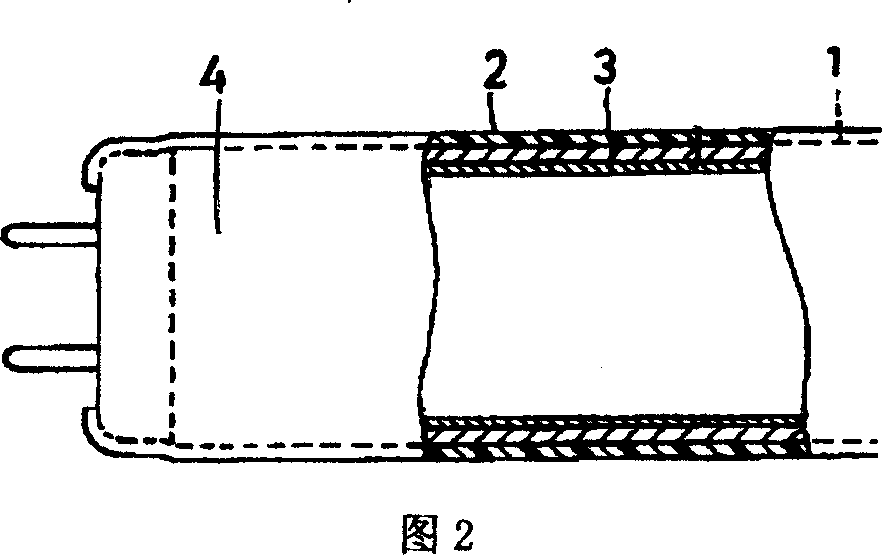
[0093] Fig. 1 shows the structure of a fluorescent lamp 4 of the present invention. Fluorescent lamp 4 can be manufactured according to usual method, for example first adopts injection method or inhalation method to inject blue-green luminescent material (Ba, Ca, Mg) 10 (PO 4 ) 6 Cl 2 : The powder slurry composed of Eu, nitrocellulose and butyl acetate is injected or inhaled into the cleaned and dried glass tube 1, so that the powder slurry flows down along the inner surface of the glass tube 1, and after drying, the first layer is formed on the inner surface of the glass tube 1. 2 light-emitting layer 2. Then use the same method to form a long-wave ultraviolet light-emitting material BaSi on the second light-emitting layer 2. 2 o 5 : Pb and orange luminescent material (Sr, Mg) 3 (PO 4 ) 2 : The first light-emitting layer 3 composed of Sn is dried and baked. Then seal the electrodes 5 at both ends of the glass tube 1, after exhausting, fill the lamp tube with argon ga...

Embodiment 2

[0095] In Example 1, the first light-emitting layer 3 is made of long-wave ultraviolet light-emitting material SrB 4 o 7 F: Eu and red luminescent material Y 2 o 3 : composed of Eu, and the second light-emitting layer 2 is made of green light-emitting material Y 2 SiO 5 : Ce, Tb and blue luminescent material Sr 10 (PO 4 ) 6 Cl 2 : Eu composition, all the other are with embodiment 1. due to Y 2 o 3 : Eu has high luminous efficiency under 254nm short-wave ultraviolet excitation, while Y 2 SiO 5 : Ce, Tb and Sr 10 (PO 4 ) 6 Cl 2 :Eu in SrB 4 o 7 F: Under the excitation of long-wave ultraviolet light (peak wavelength = 360nm) emitted by Eu, it has high luminous efficiency. Therefore, the fluorescent lamp 4 has high luminous efficiency and good color rendering.

Embodiment 3

[0097] In Example 1, the first light-emitting layer 3 is made of SrB 4 o 7 F: Eu, Y 2 o 3 :Eu and green luminescent material LaPO 4 : Ce, Tb composition, and the second light-emitting layer 2 is composed of Sr 10 (PO 4 ) 6 Cl 2 : Eu composition, all the other are with embodiment 1. Thanks to LaPO 4 : Ce, Tb also have high luminous efficiency under 254nm short-wave ultraviolet excitation, therefore, the fluorescent lamp 4 has high luminous efficiency and good color rendering.


PUM


Abstract

The invention provides fluorescent light, light-accumulation fluorescent light, lighting device and light-accumulation lighting device whose luminescence property is perfect. Firstly, the shortwave ultraviolet radiation (254nm) generated by the fluorescent light inspires long wave ultraviolet radiation or purple luminescence material, then the light omitted by the long wave ultraviolet radiation or purple luminescence material inspires other luminescence material to obtain fluorescent light, light-accumulation fluorescent light, lighting device and light-accumulation lighting device whose luminescence efficiency is high, coloration is good, color range is wide.

Description

technical field [0001] The present invention relates to a fluorescent lamp and a light-emitting device. Specifically, it relates to a fluorescent lamp with high luminous efficiency, good color rendering, and a wide color gamut, a phosphorescent fluorescent lamp, a light-emitting device, and a phosphorescent light-emitting device. Background technique [0002] Fluorescent lamps (including hot-cathode fluorescent lamps, cold-cathode fluorescent lamps, compact fluorescent lamps, electrodeless fluorescent lamps, etc.) have been widely used in indoor lighting, road lighting, urban lighting, and LCD backlights. With the expansion of the application of fluorescent lamps, people put forward the requirement of light storage, which requires the use of light-storing fluorescent lamps and light-storing light-emitting devices, which can still continue to emit light for a period of time after they stop working. [0003] Phosphorescent fluorescent lamps and phosphorescent light-emitting de...

Claims


Application Information

Patent Timeline
IPC IPC(8): H01J61/48H01J61/44C09K11/00
Inventor 邱行中尹绍刚邱励楠尹远成黎涤萍
Owner 黎涤萍
Why Eureka
Try Eureka