Multilayer printed wiring board

A multi-layer printing and circuit board technology, which is applied in the fields of printed circuit, printed circuit, printed circuit manufacturing, etc., can solve the problems of increasing the rigidity of the insulating substrate, reducing the rigidity of the mounting substrate, and easily reducing the resistance, so as to prevent the conductor circuit from breaking or Disconnection, decrease in reliability reduction, effect of reducing reliability reduction

Active Publication Date: 2007-11-07
IBIDEN CO LTD
View PDF1 Cites 20 Cited by
  • Summary
  • Abstract
  • Description
  • Claims
  • Application Information

AI Technical Summary

Problems solved by technology

[0011] In addition, although it is required to further reduce the thickness of the substrate itself used in portable electronic devices, since the thickness of the insulating layer of each layer constituting the mounting substrate is required to be 100 μm or less, even if it is multi-layered, the thickness of the entire mounting substrate itself will be reduced. It is thinner than the conventional mounting board itself, so it is easy to reduce the rigidity of the mounting board itself
[0012] In addition, since the rigidity of the board itself is lowered, the resistance to warping etc. is also likely to be lowered. As a result, the flatness of the board is easily impaired, and problems are likely to occur in subsequent processes (such as the component mounting process).
[0013] In addition, since the thickness of the insulating layer is thin, the mounting substrate itself is also soft and easily warped, so it is easily affected by stress due to external impacts, etc.
For example, although a method of improving rigidity by using insulating substrates with a thickness of 600 μm or more as the center of the insulating substrate during lamination has been studied, it may not be accommodated in a case of a portable electronic device, etc., so it becomes impossible to use it. The technical dilemma of the thickness of the insulating substrate in the center
[0014] Therefore, in the conventional multilayer circuit board for mounting as described above, since the rigidity cannot be increased by thickening the insulating substrate which is the center of lamination, it is difficult to improve the function or startability of the substrate in the drop test in the reliability test.
In particular, as described above, it is difficult to improve the reliability or the drop resistance to the drop test of the mounting substrate with increased mounting density of parts and the like.
That is, since sufficient reliability cannot be obtained in the reliability test, the electrical connectivity and reliability cannot be further improved.

Method used


Image

  • Multilayer printed wiring board
  • Multilayer printed wiring board
  • Multilayer printed wiring board

Examples


Embodiment 1

[0133] (1) First, a circuit board as a unit constituting a multilayer printed circuit board is produced. This circuit board is a substrate that is the center of lamination among a plurality of insulating layers to be laminated. A prepreg sheet that is made into a B-stage by impregnating epoxy resin on glass cloth is laminated with copper foil and heated. The double-sided copper-clad laminate 10 obtained by pressing was used as a raw material (refer FIG. 9A).

[0134] The thickness of the insulating base material 12 is 60 μm, and the thickness of the copper foil 14 is 12 μm. If a copper foil thicker than 12 μm is used as the copper foil of the laminate, the thickness of the copper foil can also be adjusted to 12 μm by etching the copper foil.

[0135] (2) Carbon dioxide gas laser irradiation is performed on the double-sided circuit board 10 having the copper foil 14, and the copper foil 14 and the insulating base material 12 are penetrated to form the opening 16 for forming a ...

Embodiment 2

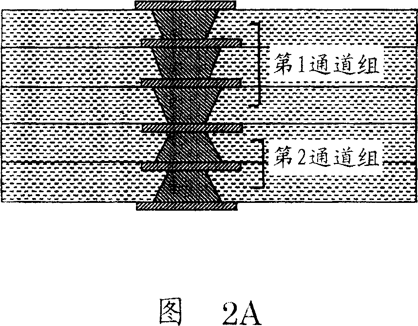
[0193] Each via hole constituting the first channel group and the second channel group formed on the insulating layer laminated on the surface and the back surface of the above-mentioned double-sided circuit board respectively, as shown in FIG. A multilayer printed wiring board was manufactured in substantially the same manner as in Example 1 except that the position was formed at a distance of about 1 / 2.

Embodiment 3

[0195] Each via hole that constitutes the first channel group formed on the above-mentioned double-sided circuit board and the insulating layer stacked above it, and the second channel group formed on the insulating layer stacked below the double-sided circuit board, as shown in the figure As shown in 3B, a multilayer printed wiring board was manufactured in substantially the same manner as in Example 1, except that the via hole diameters were substantially shifted from each other.


PUM

PropertyMeasurementUnit
thicknessaaaaaaaaaa
thicknessaaaaaaaaaa
thicknessaaaaaaaaaa

Abstract

A multilayer printed wiring board comprises a plurality of insulating layers which is about 100 mum or less in thickness and a plurality of conductor circuits formed on the insulating layers. Each of a plurality of viaholes electrically connecting conductor circuits on the insulating layers to each other is formed tapered inwardly from the surface of the insulating layer and the viaholes are disposed opposite to each other to form a multistage stacked vias.

Description

technical field [0001] The present invention relates to a multilayer printed circuit board for mounting electronic components such as capacitors and ICs on the surface. Specifically, it relates to a multilayer printed circuit that does not cause the electronic components to fall off or reduce electrical connectivity and reliability due to dropping. plate. Background technique [0002] In portable electronic devices such as mobile phones and digital cameras in recent years, miniaturization of mounting parts is sought in response to their high-function and high-density requirements. In addition, for the substrate, by reducing the wiring density (wiring line width / wiring space gap), or measures to reduce the size of the pad, etc., can also correspond to the high density of the mounted parts. [0003] As components mounted on such substrates, specifically, passive components such as IC chips, capacitors, resistors, and inductor coils, liquid crystal devices, display devices for...

Claims


Application Information

Patent Timeline
Patent Type & Authority Applications(China)
IPC IPC(8): H05K3/46
CPCY10T29/49124H05K2201/09709H05K1/115H05K2201/0394H05K2201/0352H01L2924/0002H05K2201/096H05K2201/09563H05K3/4652H05K3/4602H05K2201/09827H01L2924/00H05K3/46H01L23/48H05K3/00
Inventor 高桥通昌三门幸信中村武信青山雅一
Owner IBIDEN CO LTD
Why Eureka
Try Eureka