Corrugated pattern forming sheet and method for manufacturing the same, and method for manufacturing antireflector, retardation plate, original process sheet plate, and optical element

A manufacturing method and technology of optical components, applied in the directions of optical components, optics, polarizing components, etc., can solve the problems of difficult processing, unsuitable for mass production, etc., and achieve the effect of low reflectivity and excellent performance

Inactive Publication Date: 2007-11-14
OJI HLDG CORP
View PDF6 Cites 18 Cited by
  • Summary
  • Abstract
  • Description
  • Claims
  • Application Information

AI Technical Summary

Problems solved by technology

However, when using ultraviolet laser interferometry or electron beam exposure, there are problems in that it is difficult to process in a wide area exceeding 10 cm, and it is not suitable for mass production.
However, this method also has the following problems: it is difficult to process in a wide area exceeding 30 cm, and it is not suitable for mass production

Method used


Image

  • Corrugated pattern forming sheet and method for manufacturing the same, and method for manufacturing antireflector, retardation plate, original process sheet plate, and optical element
  • Corrugated pattern forming sheet and method for manufacturing the same, and method for manufacturing antireflector, retardation plate, original process sheet plate, and optical element
  • Corrugated pattern forming sheet and method for manufacturing the same, and method for manufacturing antireflector, retardation plate, original process sheet plate, and optical element

Examples


manufacture example 1

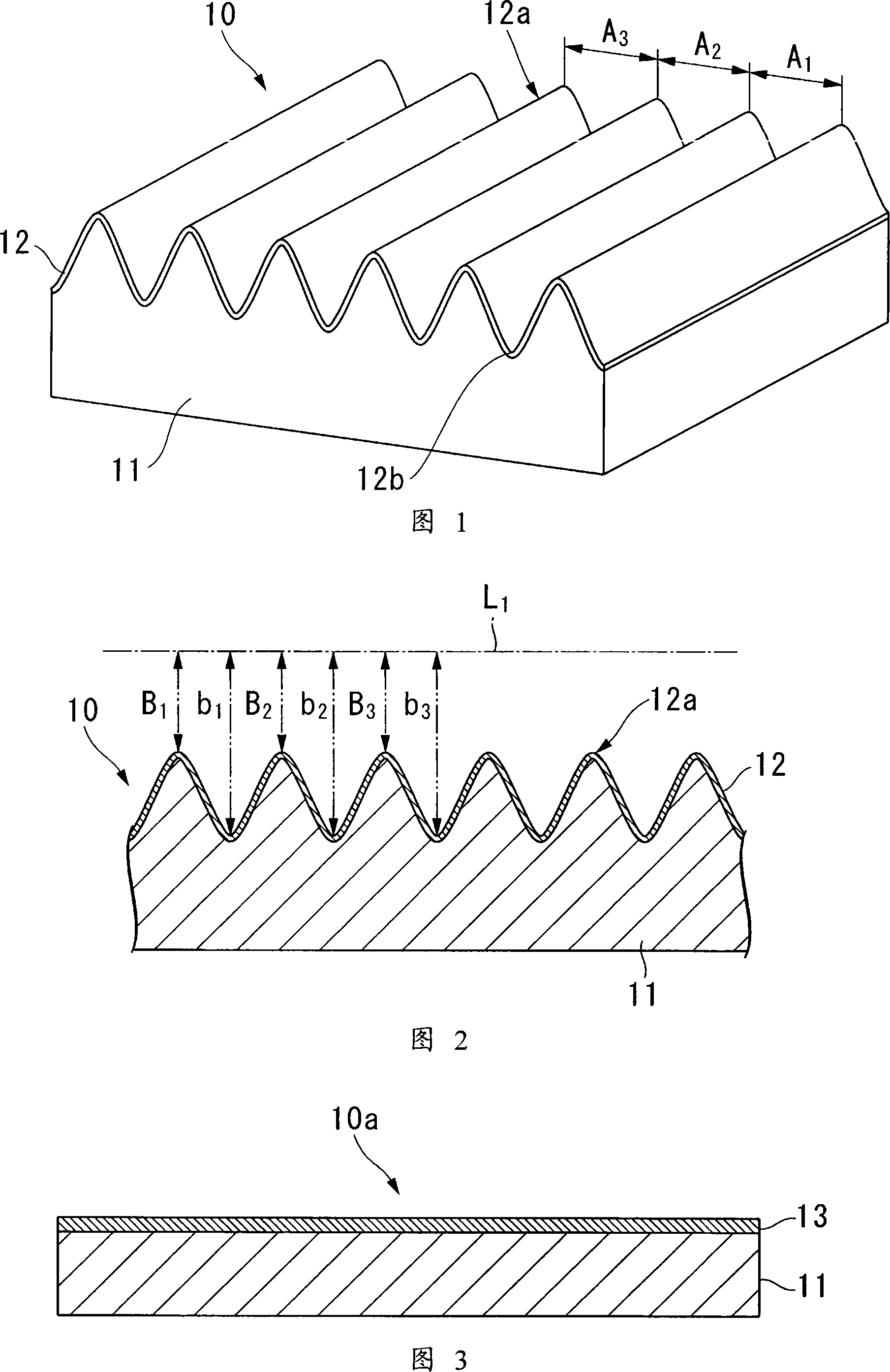
[0189] On one side of a polyethylene terephthalate shrink film with a thickness of 50 μm and a Young's modulus of 3 GPa (Hishpet LX-10S manufactured by Mitsubishi Plastics Co., Ltd.), which is thermally shrunk in one axial direction, vacuum deposition with a Young's modulus of 115 GPa Titanium, the thickness of which is 3nm, forms a hard layer with a smooth surface to obtain a laminated sheet.

[0190] Next, heat the laminated sheet at 100° C. for 1 minute to make it thermally shrink to 40% of the length before heating (that is, to deform at a deformation rate of 60%), and obtain a rigid layer perpendicular to the relative shrinkage direction. A concave-convex shape forming sheet that forms a periodically wavy concave-convex shape in a direction.

manufacture example 2

[0192] A concavo-convex shape-formed sheet was obtained in the same manner as in Production Example 1 except that the thickness of the vacuum-deposited titanium was 7 nm.

manufacture example 3

[0194] The laminated sheet was heated at 75° C. for 1 minute to heat-shrink to 70% of the length before heating (that is, deformed at a deformation rate of 30%). In the same manner as in Production Example 1, a concavo-convex shape was obtained. Form into pieces.


PUM

PropertyMeasurementUnit
thicknessaaaaaaaaaa
thicknessaaaaaaaaaa
thicknessaaaaaaaaaa

Abstract

A corrugated pattern forming sheet exhibiting excellent performance when being used as optical elements, such as an antireflector and a retardation plate is provided. A corrugated pattern forming sheet of the invention includes a resin layer, and a hard layer provided at least in a portion of an outer surface of the resin layer. The hard layer is made of a metal or a metallic compound. The hard layer has a wavelike corrugated pattern. The average pitch of the corrugated pattern is 1 mum or less, and the average depth of the bottom of the corrugated pattern is 10% or more given an average pitch of 100%.

Description

technical field [0001] The present invention relates to a concavo-convex shape forming sheet included in optical elements such as an anti-reflector and a retardation plate, and a method for manufacturing the same. It also relates to an anti-reflection body and a phase difference plate using a concave-convex shape forming sheet. It also relates to a process sheet master used as a mold for manufacturing a sheet formed with concavo-convex shapes. It further relates to a method of manufacturing the optical element. Background technique [0002] As an optical element such as an anti-reflector and a phase difference plate, it is known that a concave-convex shape forming sheet can be used. On the surface of the concave-convex shape forming sheet, a concave-convex shape composed of fine wave-like concave-convex is formed. wavelength or less (see Non-Patent Document 1). [0003] Here, the average pitch refers to the average value of the distance between the top of a convex portion...

Claims


Application Information

Patent Timeline
Patent Type & Authority Applications(China)
IPC IPC(8): G02B5/00G02B1/00G02B5/30G03F1/00G03F7/00
Inventor 冈安俊树
Owner OJI HLDG CORP
Why Eureka
Try Eureka