Erecting equipment remote actual time safety monitoring system and its control method

A lifting equipment and monitoring system technology, applied in the direction of load hanging components, transportation and packaging, etc., can solve the problems of lifting equipment that cannot be remotely monitored in real time, low accuracy, and complicated and difficult human supervision

Inactive Publication Date: 2007-11-28
SHENZHEN ZHONGXINKANG SPECIAL EQUIP TECH
View PDF0 Cites 49 Cited by
  • Summary
  • Abstract
  • Description
  • Claims
  • Application Information

AI Technical Summary

Problems solved by technology

[0004] In order to solve the problems that the existing lifting equipment cannot carry out remote real-time monitoring, human supervision is complicated and difficult, the accuracy is low, the effectiveness is poor, and the safety factor is low, the present invention provides a lifting equipment remote real-time safety supervision system and its control method

Method used


Image

  • Erecting equipment remote actual time safety monitoring system and its control method
  • Erecting equipment remote actual time safety monitoring system and its control method
  • Erecting equipment remote actual time safety monitoring system and its control method

Examples


Embodiment 1

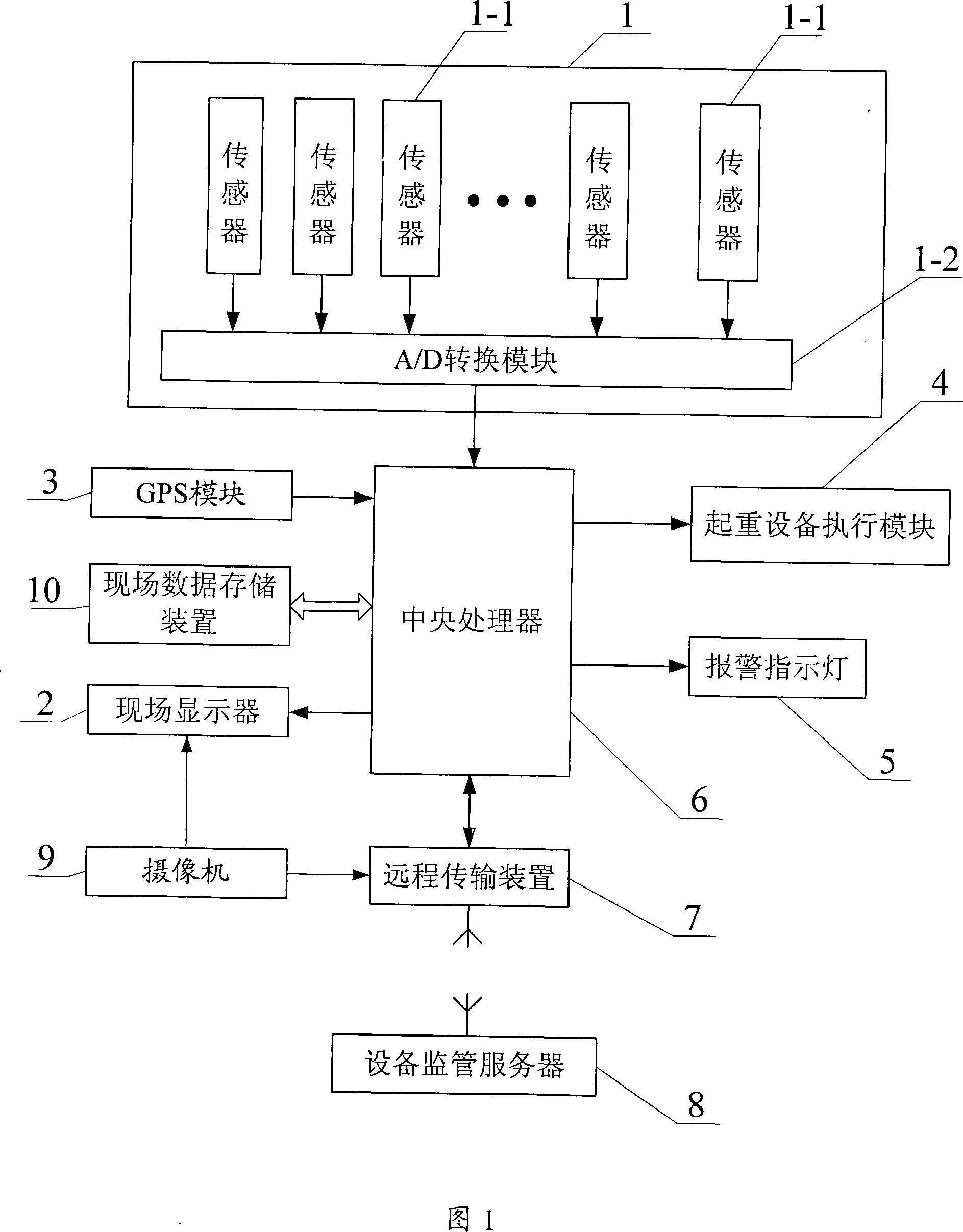
[0038] Embodiment 1: As shown in FIG. 1 , the supervisory system of this specific embodiment includes a sensing signal acquisition device 1 for detecting various parameter information of the lifting equipment, a central processing unit 6, a lifting equipment execution module 4, and a remote transmission device 7. Equipment supervision server 8, on-site display 2, on-site data storage device 10 and alarm indicator light 5; a plurality of signal output ends of the sensing signal acquisition device 1 are respectively connected to a plurality of sensing signals of the central processing unit 6 Input terminal; the lifting equipment execution signal output end of the central processing unit 6 is connected to the input end of the lifting equipment execution module 4, and the lifting equipment execution module 4 receives the lifting equipment execution of the central processing unit 6 The signal is used to control the action of the lifting equipment; the data transmission end of the re...

Embodiment 2

[0042] Embodiment two: as shown in Figure 1, on the basis of embodiment one: the supervisory system also includes a camera 9, the video information output end of the camera is respectively connected to the image data of the on-site display and the remote transmission device input. By adopting the specific implementation mode, it is convenient for the operator to obtain the actual operating conditions on the boom of the crane more intuitively, and to control the lifting equipment more effectively. For example, as shown in Figure 6, a 27-fold automatic integrated auto-focus camera can be used on the tower crane, and installed under the luffing trolley of the tower crane, aligned with the hook, to monitor the hoisting situation of the tower crane at all times . Due to the frequent movement of the luffing trolley, a special set of video cable connection device is required. As shown in Figure 6, the lower chord 11 is a square steel pipe, and the root and front end of the jib are ...

Embodiment 3

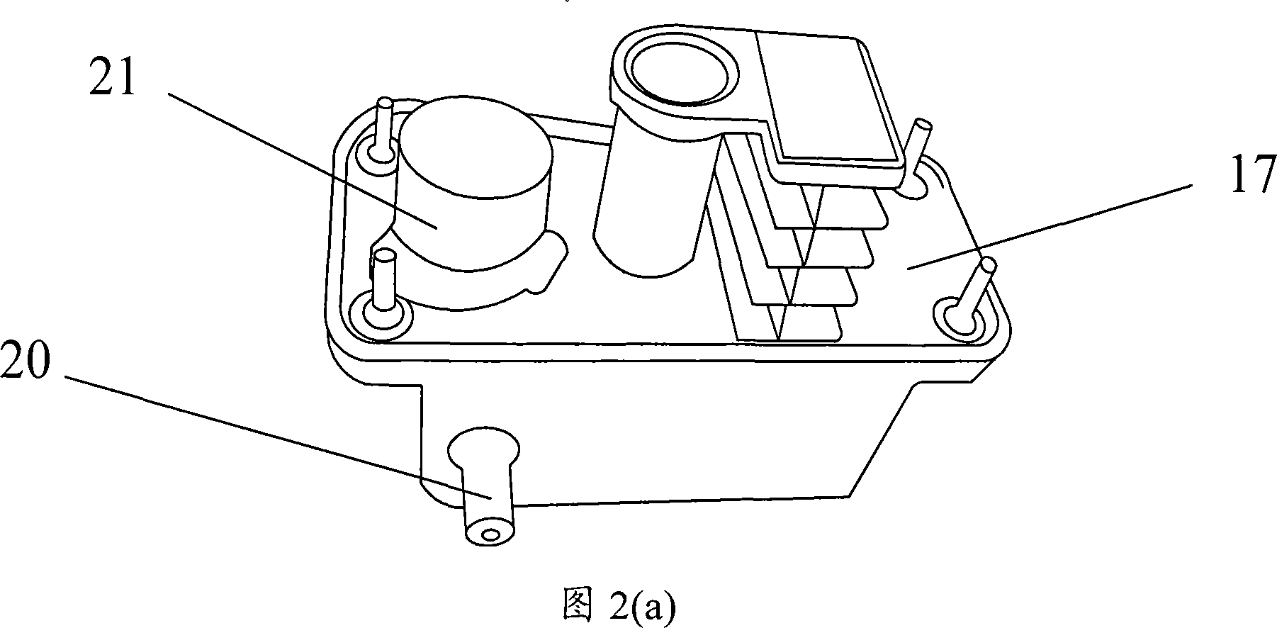
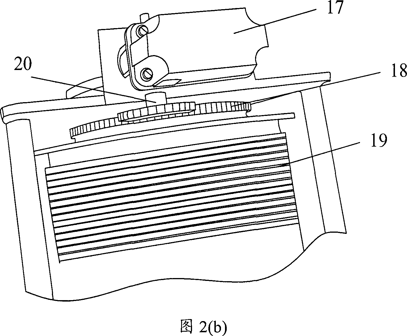
[0043] Embodiment 3: As shown in FIG. 1 , on the basis of Embodiment 1: the sensing signal acquisition device 1 includes a plurality of sensors 1-1 and A / D conversion modules 1-2, and the plurality of sensors 1 -1 The parameter signals measured respectively are processed by the A / D conversion module 1-2 and sent to the central processing unit 6 . The plurality of sensors 1-1 includes a plastic potentiometer, which is installed in the stroke limiting device of the lifting equipment, and the signal input end of the plastic potentiometer is connected to the detection signal input end of the stroke limiting device . The plastic potentiometer is used to measure the height and range of the lifting equipment in real time; if the lifting equipment uses a multi-function limiter to limit the height and range, the plastic potentiometer can be installed inside the multi-function limiter , the plastic potentiometer can be a potentiometer with a model number of WDD35D-4. As shown in Fig. ...


PUM


Abstract

The present invention discloses remote real-time safety monitoring system for hoisting apparatus and its control method. The present invention has a remote transmission device for data transmission with the upper monitoring server, and a sensing signal acquirer for real-time acquisition of the parameter information of the hoisting apparatus. The control method is to adopt several parallel remote control threads for data processing, and includes the first setting the received data into idle data processing queue with the data monitoring and processing thread and the subsequent processing the data in the queue with the data statistics and saving thread. The monitoring system of the present invention can realize critical state alarm and emergency state control as well as understand the running state of the hoisting apparatus remotely.

Description

technical field [0001] The invention relates to the field of hoisting machinery and control, in particular to a system capable of remote monitoring of hoisting equipment and its control method. Background technique [0002] At present, most of the lifting equipment used in China is not equipped with online safety monitoring devices, especially the lifting equipment used on construction sites. They are only equipped with simple safety devices: such as tower cranes, using weight (moment) limiters To control the limit value of weight and moment, and to control the limit value of amplitude / height by using the multi-functional limiter, the crane operator cannot see the actual weight of the hoisted object, the position of the trolley and the lifting height intuitively in real time, only The operation can be completed by the naked eye, experience, and command, which has great blindness, low accuracy, poor effectiveness, and low security. Moreover, the lifting capacity limiter and ...

Claims


Application Information

Patent Timeline
Patent Type & Authority Applications(China)
IPC IPC(8): B66C13/40B66C13/16
Inventor 汤冠群
Owner SHENZHEN ZHONGXINKANG SPECIAL EQUIP TECH
Why Eureka
Try Eureka