Method for embedding cement purdah into prefabricated reinforced concrete anti-lateral-force pile

A technology for resisting lateral force and mixing soil, applied in excavation, construction, infrastructure engineering, etc., can solve the problems of construction mud pollution, unstable construction quality, slow construction speed, etc., to achieve reliable quality, fast construction speed, The effect of comprehensive cost saving

Inactive Publication Date: 2007-11-28
严平 +1
View PDF0 Cites 15 Cited by
  • Summary
  • Abstract
  • Description
  • Claims
  • Application Information

AI Technical Summary

Problems solved by technology

[0003] The reinforced concrete round pile is a traditional construction method, which has the disadvantages of high cost, slow construction speed, and environmental pollution from constructi

Method used


Image

  • Method for embedding cement purdah into prefabricated reinforced concrete anti-lateral-force pile
  • Method for embedding cement purdah into prefabricated reinforced concrete anti-lateral-force pile
  • Method for embedding cement purdah into prefabricated reinforced concrete anti-lateral-force pile

Examples


Embodiment 1

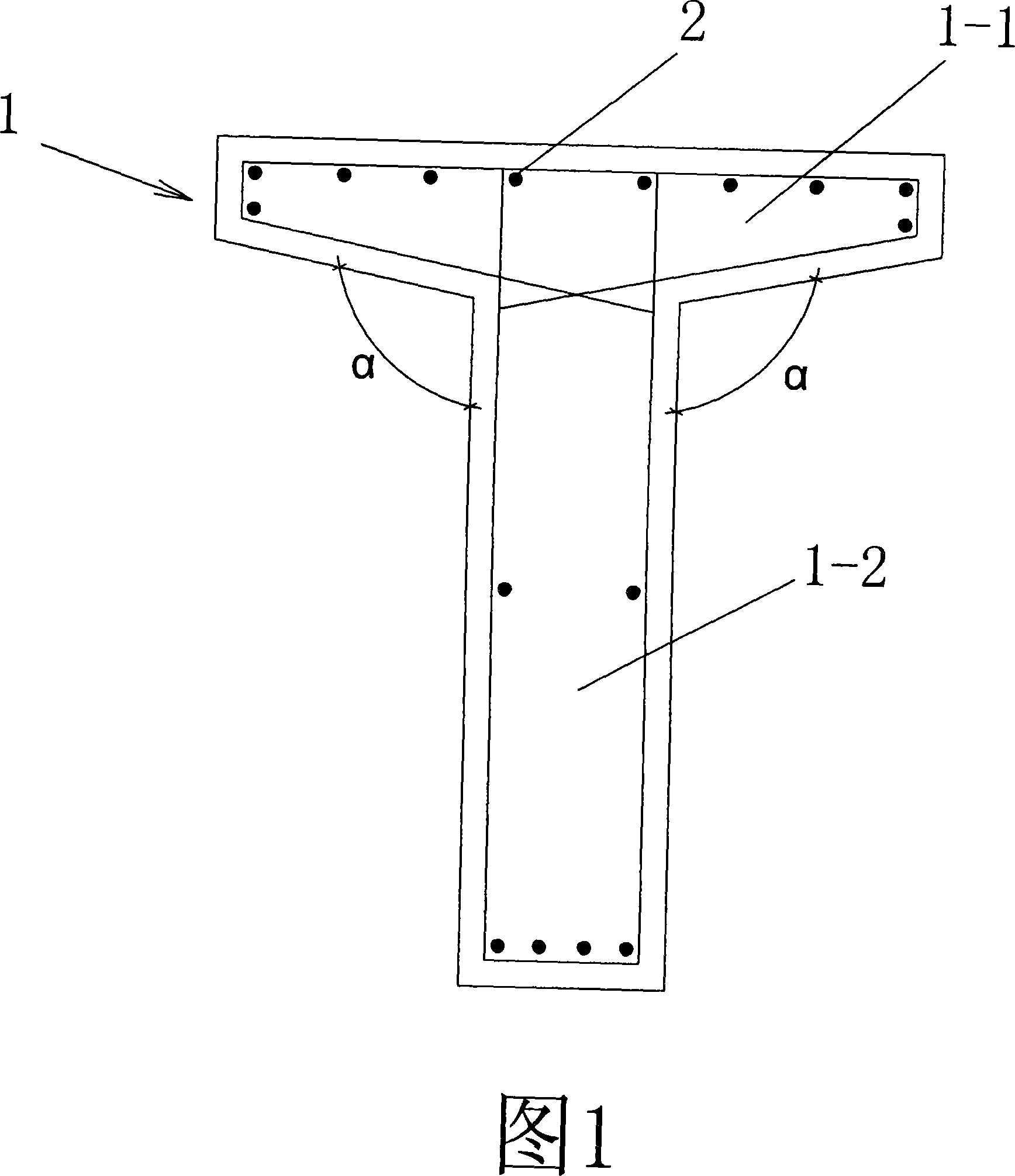
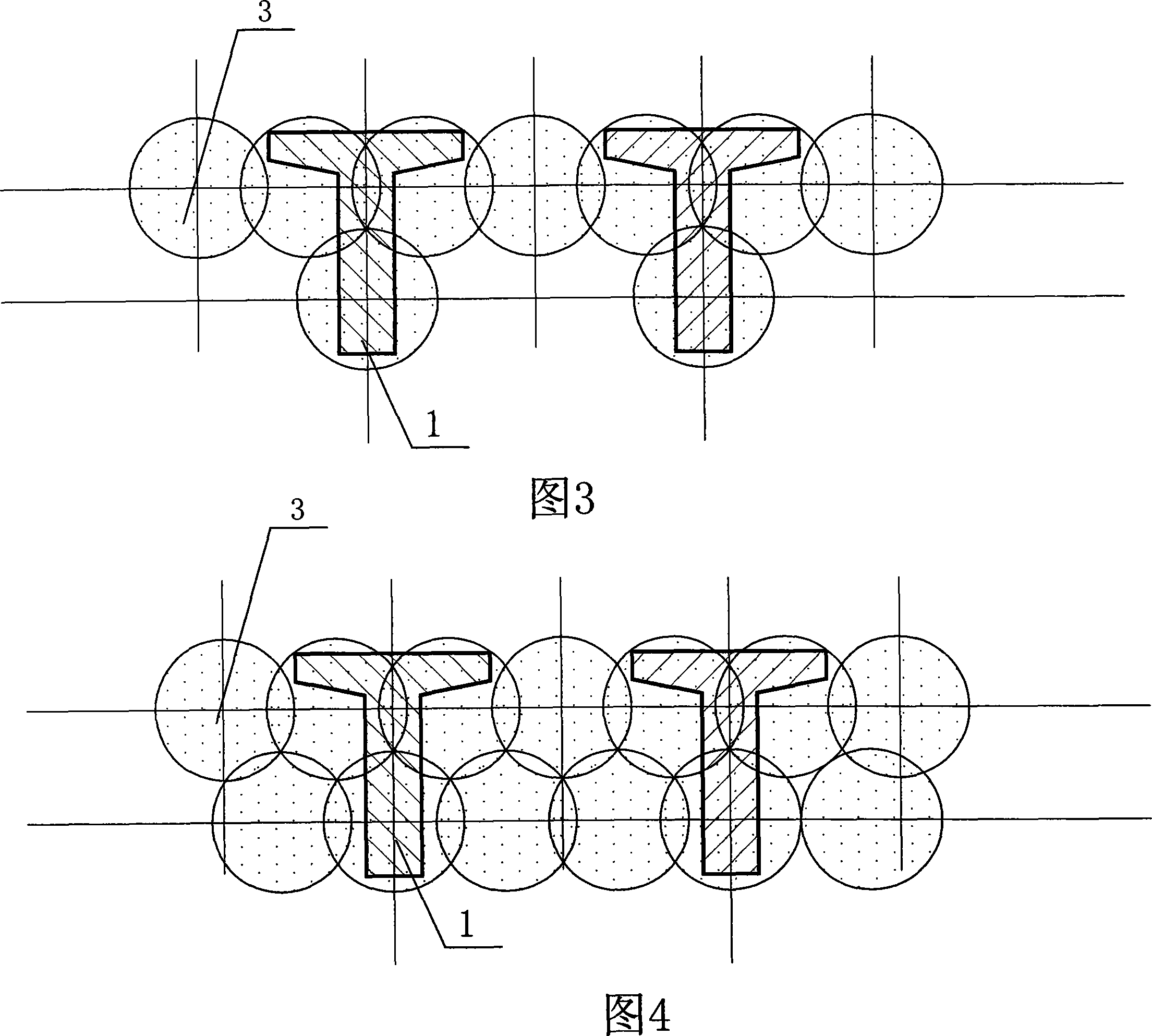
[0026] Embodiment 1: the method for implanting the prefabricated reinforced concrete anti-lateral force T-shaped / I-shaped pile with this cement mixing soil curtain mainly comprises the following steps: at the construction site, earlier use the cement mixer along the implantation depth of the pile body 1, depending on the Soil quality and soil compaction conditions, mixing the soil in the whole process or part of the upper water-stop curtain to form various mixing pile curtains 3, and then using a pile driver to implant the pile body 1 to form the soil-retaining and water-stop required for various enclosure projects enclosure wall. Among them, Figure 3 is a single row of small diameter mixing pile curtain, Figure 4 is a double row of small diameter mixing pile curtain, Figure 5 is a single row of large diameter mixing pile curtain, Figure 6 is an arched mixing pile curtain, Figure 7 is a mixing pile curtain Insert curtains such as moso bamboo 4, wooden stakes, steel pipes, etc....

Embodiment 2

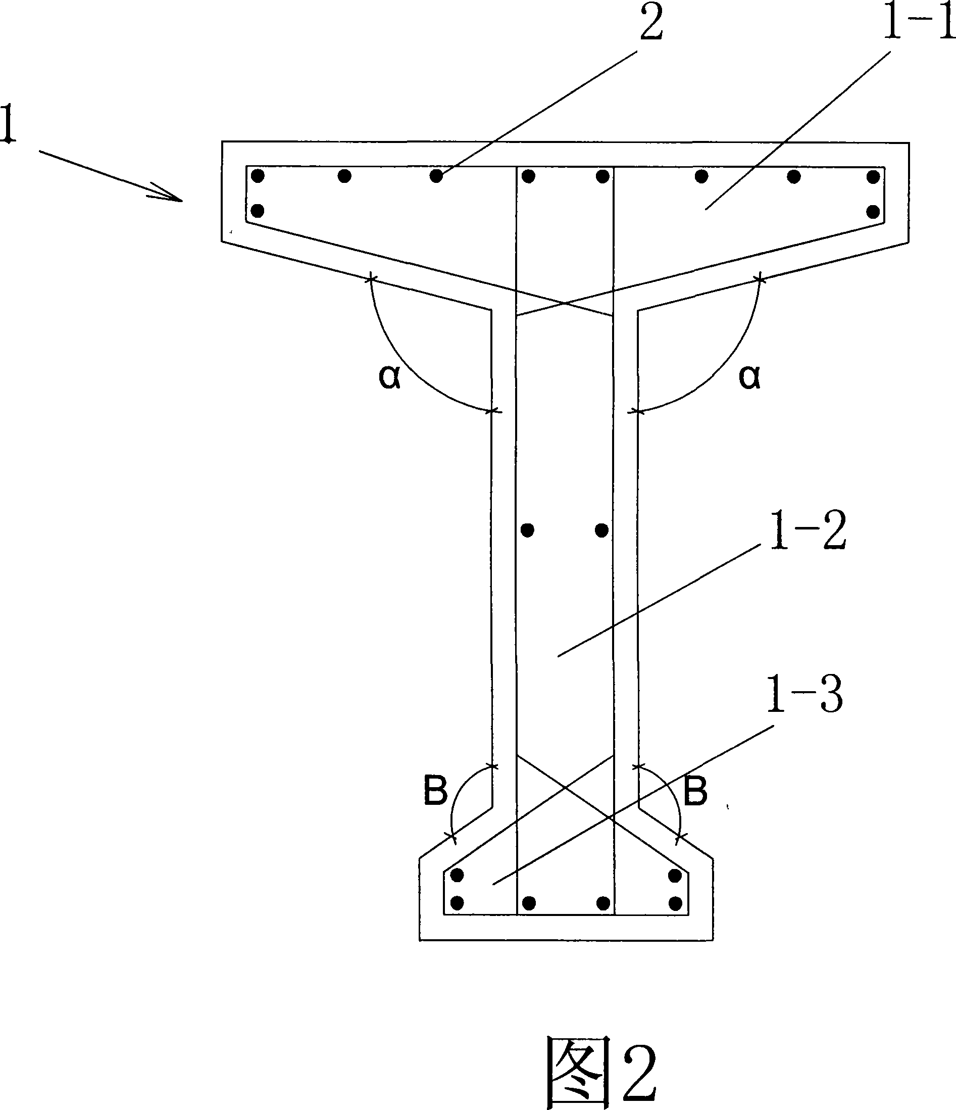
[0029] Embodiment 2: As shown in Figure 2, the difference from Embodiment 1 is that the other end of the web 1-2 is connected with a second wing plate 1-3 and forms an I-shaped shape, and the second wing plate 1-3 The included angle β with both sides of the web 1-2 is greater than 90° and less than 135°.

[0030] As shown in Figure 8.9.10.11.12, the cement mixer is mixed to form a curtain of various mixing piles matching the size of the I-shaped piles, and various required enclosure walls are formed after the I-shaped prefabricated piles are implanted. Among them, Figure 8 is a curtain of single row of small diameter mixing piles, Figure 9 is a curtain of double rows of small diameter mixing piles, Figure 10 is a curtain of single row of large diameter mixing piles, Figure 11 is a curtain of arched mixing piles, Figure 12 is a curtain of mixing piles Moso bamboo, wood piles, steel pipes and other curtains are inserted.


PUM


Abstract

The invention relates to a method that cement mixed soil curtain implants lateral force resistance pile of prefabricated reinforced concrete. Main procedures are described as follows. In construction site, cement mixer is used to mix soil in the whole journey or in upper water-stopping curtain part to form curtain along the implanting depth aiming to soil quality and soil extruding status; then it is implanted into pile body by pile driver to form retaining and waterproof enclosure wall. Thereinto pile body adopts prefabricated reinforced concrete T-shape/ I-shape pile. Because powerful mixing soil or drilling machine is used to dig hole and inject grout, it is suitable for enclosure project of all kinds of soil qualities in principle. The beneficial effect of invention is that reinforcement ribs of T-shape or I-shape section are located at two ends of section; compared with circular pile with reinforcement ribs distributed along round face, the bending strength can be improved by more than 20% and the section area only is half of corresponding circular pile, namely concrete amount is saved in half. Ant it is provided with rapid construction speed, reliable quality, no noise and no pollution to circumstance by carrying slurry out so on.

Description

technical field [0001] The invention relates to a construction method of T-shape / I-shape anti-lateral force reinforced concrete used for enclosure engineering and slope stability engineering, in particular to a cement-mixed soil curtain implanted with prefabricated reinforced concrete anti-lateral force piles Methods. Background technique [0002] At present, in the foundation pit enclosure engineering and slope stabilization engineering, the enclosure wall formed by reinforced concrete round piles combined with cement mixing piles is often used, and vibrating sinking tube T-shaped piles are used instead of round piles or SMW construction method (planting in cement mixing soil) is often used. into recyclable large I-shaped steel to form the enclosure wall). [0003] The reinforced concrete round pile is a traditional construction method, which has the disadvantages of high cost, slow construction speed, and environmental pollution from construction mud; the SMW construction...

Claims


Application Information

Patent Timeline
IPC IPC(8): E02D17/20
Inventor 严平
Owner 严平
Why Eureka
Try Eureka