
Heat pump generator or engine

A heat pump and generator technology, applied in machines/engines, heat pumps, refrigerators, etc., can solve problems such as low thermal energy transfer rate, large amounts of exhaust gas, dust, and environmental pollution

Inactive Publication Date: 2007-11-28
成坚强
View PDF0 Cites 2 Cited by
  • Summary
  • Abstract
  • Description
  • Claims
  • Application Information

AI Technical Summary

Problems solved by technology

It needs to burn coal, oil or nuclear reaction to produce steam. During the combustion process, a large amount of exhaust gas and dust are produced, polluting the environment, and the heat transfer rate is low.

Method used


Image

  • Heat pump generator or engine
  • Heat pump generator or engine

Examples


Embodiment 1

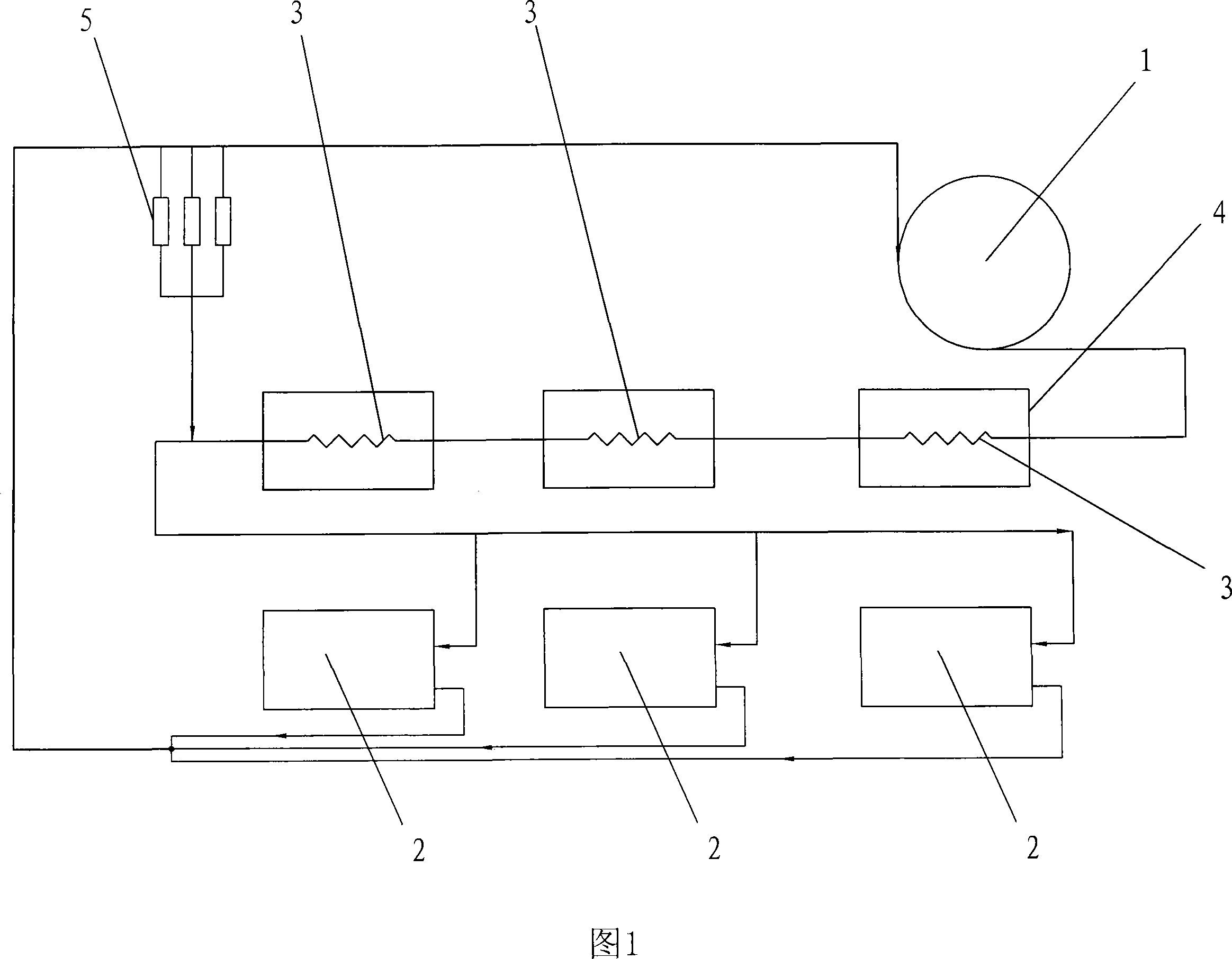
[0011] As shown in Figure 1, a single refrigerant system: a heat pump generator or engine includes a steam turbine 1, a generator or an engine (not shown in the figure), three condensers 3, three condensate tanks 4, and three heat pumps Or the unit 2 and the oil separation device 5, the steam turbine 1 and the condenser 3, the condenser 3 and the heat pump or unit 2, the heat pump or unit 2 and the steam turbine 1 are connected by pipes, and the refrigerant is carried in the pipes; the condenser 3 is immersed in the condensing In the water tank 4 , the oil separation device 5 is connected to the pipeline between the heat pump machine or unit 2 and the steam turbine 1 , and between the condenser 3 and the heat pump machine or unit 2 .

[0012] The condensers 3 are connected in series, and each condenser 3 is individually immersed in the water of the condensed water tank 4; the three heat pump machines or units 2 are connected in parallel.

[0013] Heat pump machine or unit 2, c...

Embodiment 2

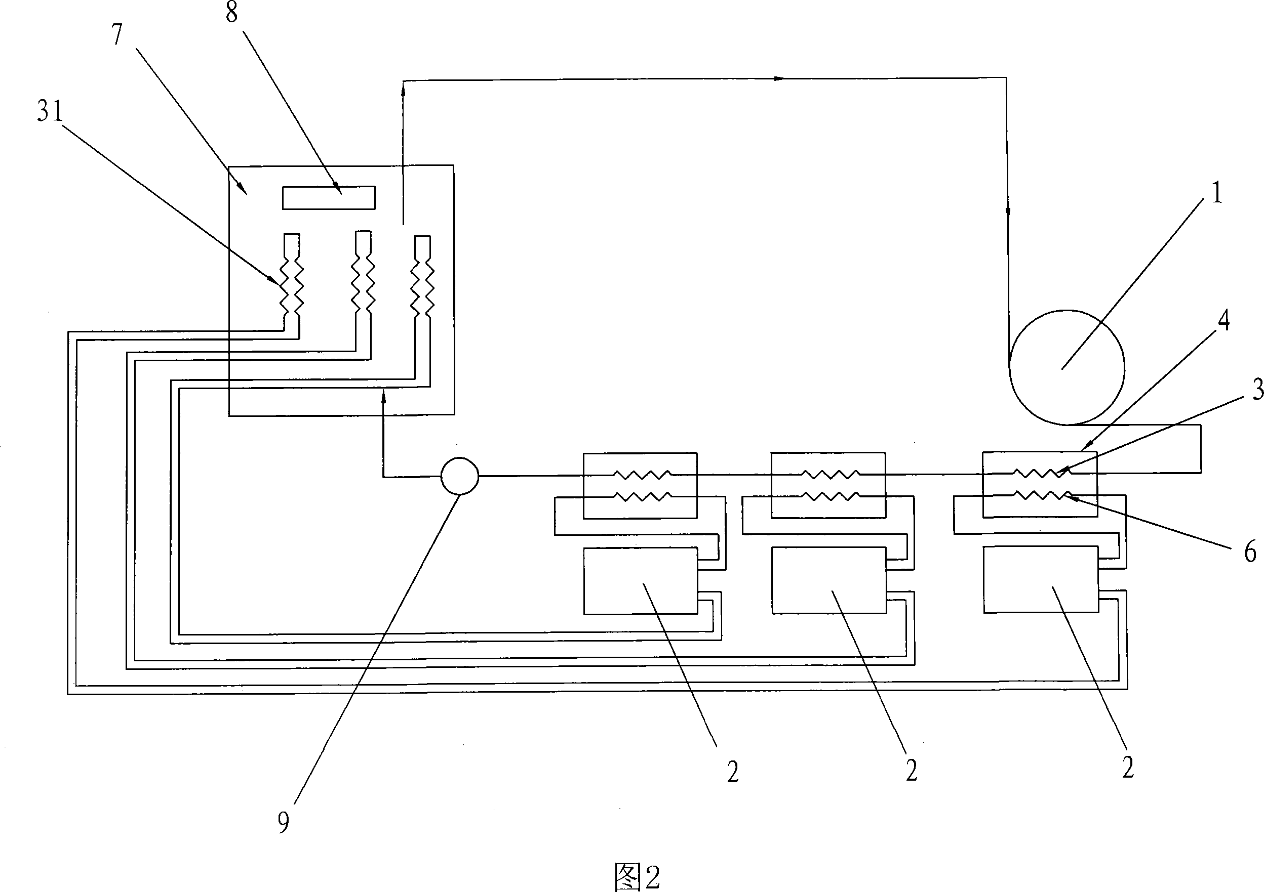
[0016] As shown in Figure 2, dual refrigerant system: this heat pump generator or engine includes a steam turbine 1, a generator or engine (not shown in the figure), three condensers 3, three condensate water tanks 4, and three evaporators 6. Three heat pumps or units 2 and steam boiler 7, steam turbine 1 and condenser 3, condenser 3 and steam boiler 7, steam boiler 7 and steam turbine 1 are connected by pipes, and steam boiler 7 uses refrigerant; condenser 3 Immersed in the water in the condensed water tank 4, a refrigerant pressure pump 9 is connected between the steam boiler 7 and the condenser 3; the condenser 31 and the evaporator 6 of the heat pump system are connected to the heat pump machine or unit 2, and the evaporator 6 is immersed in the condensed water tank 4, the heat pump system condenser 31 is installed in the steam boiler 7.

[0017] Three condensers 3 are connected in series, and each condenser 3 is individually immersed in a condensed water tank 4; there is ...


PUM


Abstract

The invention relates to a generator or engine of heating pump, comprising condenser, condensing water tank, heating pump machine or heating pump unit and oil separation device. The steam turbine is connected with the condenser by pipes. The condenser is connected with the heating pump machine or heating pump unit by pipes. The heating pump machine or heating pump unit is connected with the steam turbine by pipes. Cool medium is injected in the pipe. The oil separation device is connected with the heating pump machine or heating pump unit and the steam turbine by pipes. The condenser is connected with the heating pump machine or heating pump unit by pipes. Because of adopting the structure, when it is used cool medium with high temperature and high pressure drives generator or engine by the steam turbine. Cool medium enters into the condenser. Heat energy from condenser makes the temperature of water in condensing water tank rise so as to produce hot water. In working process of heating pump machine or heating pump unit. Heat energy in air is absorbed and cool air is generated. So not only conversion rate of heat energy is high but also hot water and cool air can be generated and exhaust gas and dust can not be generated.

Description

technical field [0001] The invention relates to a steam generator or engine, in particular to an air energy, water source and ground source heat pump generator or engine. Background technique [0002] In the current prior art, the composition of steam generators or engines includes: steam boilers, steam turbines, generators (or engines). It needs to burn coal, oil or nuclear reaction to produce steam. During the combustion process, a large amount of exhaust gas and dust are produced, polluting the environment, and the heat transfer rate is low. Contents of the invention [0003] The purpose of the present invention is to provide a heat pump generator or engine, which not only has a high conversion rate of heat energy, but also can produce hot water and cold air, and has no waste gas and dust, so as to achieve high efficiency, energy saving and environmental protection. [0004] The present invention is achieved in this way: a heat pump generator or engine includes: a heat...

Claims


Application Information

Patent Timeline
IPC IPC(8): F01K11/02F25B30/02F24H4/02
Inventor 成坚强
Owner 成坚强
Learn More