U-shape tube type heat exchanger

A heat exchanger and U-shaped tube technology, applied in the field of heat exchangers, can solve the problems of high manufacturing cost, low heat exchange efficiency, complicated structure of the heat exchanger, etc., to save manufacturing cost, enhance heat exchange, and improve emission performance The effect of the indicator

Active Publication Date: 2007-11-28
辽宁联友博科技有限公司
View PDF0 Cites 12 Cited by
  • Summary
  • Abstract
  • Description
  • Claims
  • Application Information

AI Technical Summary

Problems solved by technology

[0005] The first type is the plate-fin heat exchanger, which is composed of many thin plates and the secondary surface between the plates. The secondary surface not only acts as a ribbed surface, but also plays the role of tube-sheet spacing and enhances rigidity. This type of heat exchanger The structure of the switch is complex and the manufacturing cost is high
[0006] The second type is the shell-and-tube heat exchanger, and the shell-and-tube heat exchanger is provided with many parallel tubes in a cylindrical shell (these parallel tubes are called tube bundles), and the hot and cold fluids are separated from the space in the tubes. (tube side) and the space outside the tube (shell side) flow through for heat exchange; usually a longitudinal partition parallel to the tube bundle or a baffle perpendicular to the tube bundle is installed on the shell side; to increase the flow velocity of the fluid and enhance the disturbance, Improve heat transfer efficiency; this type of heat exchanger has a simple structure, but the heat transfer efficiency is low

Method used


Image

  • U-shape tube type heat exchanger
  • U-shape tube type heat exchanger
  • U-shape tube type heat exchanger

Examples


Embodiment 1

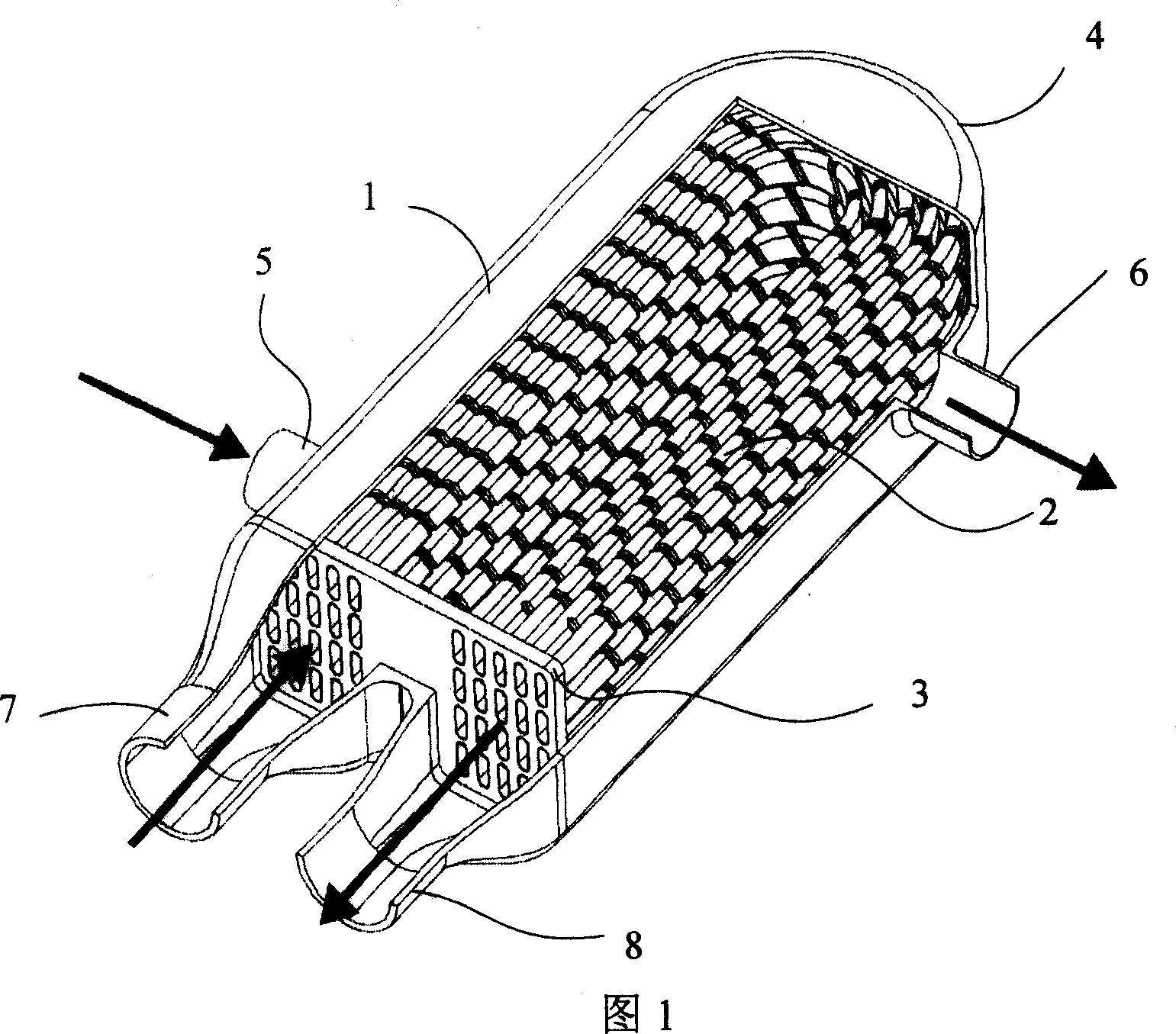
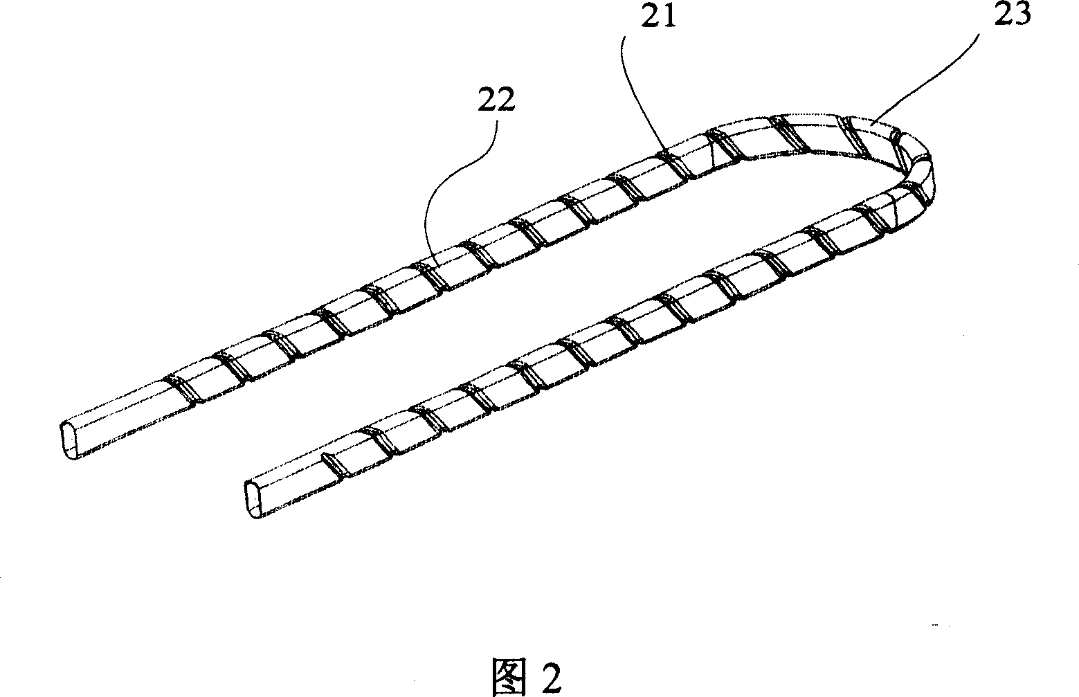
[0038] Referring to Fig. 1 and Fig. 2, an opening is provided at one end of the shell 1, and a tube plate 3 is provided at the opening, the side of the tube plate 3 facing the shell is the inner side, and the two ends of the outer sides of the tube plate 3 are respectively connected with exhaust gas inlets The connection between the pipe 7 and the exhaust gas outlet pipe 8, the inlet pipe 7 and the outlet pipe 8 and the tube plate 3 is trumpet-shaped; there is a fixed U-shaped heat exchange tube on the end surface of the inlet pipe 7 and the outlet pipe 8 of the tube plate 3 2; the heat exchange tube 2 is composed of two equal-length straight pipe sections 22 and a curved section 23 smoothly connected, and the shape is U-shaped; the two nozzles on the U-shaped heat exchange tube 2 are respectively welded on the corresponding The through holes on the corresponding tube sheets 3 are fixed in the shell 1 parallel to each other; the cooling medium inlet 5 is provided on the shell 1...

Embodiment 2

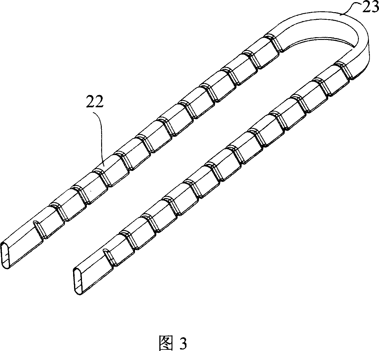
[0042] Referring to FIG. 1 and FIG. 3 , in order to reduce processing difficulty, no spiral groove is provided at the bending section 23 of the U-shaped heat exchange tube 2 fixed in the housing 1 .

[0043] Referring to Fig. 4 to Fig. 8, the vertical section of the U-shaped heat exchange tube 2 fixed in the housing 1 can have various shapes.

[0044]The heat exchange tubes arranged in the shell 1 with a flat cross-sectional shape and spiral grooves are compared with the circular heat exchange tubes with spiral grooves in the cross-sectional shape: First, when the cross-sectional area of ​​the heat exchange tubes is constant and the flow rate of the heat exchange medium is not Under the premise of changing, the cross-sectional perimeter of the flat tube is larger than that of the round tube, so the heat transfer area of ​​the flat tube is larger than that of the round tube, which in turn increases the heat transfer area of ​​the entire heat exchanger. Under the premise that th...

Embodiment 3

[0046] Referring to Fig. 1 and Fig. 4, the U-shaped heat exchange tube 2 fixed in the housing 1 is a U-shaped heat exchange tube 2 with the first cross-sectional shape shown in Fig. 4, and the cross-section of the U-shaped heat exchange tube 2 is flat. The two relatively long sides 25 are straight lines, and the two opposite short sides 24 are arc-shaped protrusions from the inside to the outside, and are connected with the long sides 25 in an arc-shaped transition. Such a setting makes full use of the surface of the heat exchange tube to achieve Maximum efficiency of heat exchange, and easy production and processing.


PUM


Abstract

The invention relates to a U-shape pipe heat exchanger suitable for exhaust gas recirculation cooling device in automobile engine system. The invention comprises shell and heat exchanging pipe. On the shell one end is opened and at the position of port pipe plate is set. Inlet and outlet pipes of heat exchanging medium are connected on the pipe plate. Via holes for fixing U-shape heat exchanging pipes are set at connecting ports of inlet and outlet pipes on the pipe plate. The heat exchanging pipe is constituted by elbow and straight pipe to form U-shape. Two pipe ports f said heat exchanging pipe are welt on the pipe plate and corresponding fixing via hole and they are fixed in shell in parallel. The invention can improve heat exchanging efficiency by 25-40%, decrease emission of NOx in automobile engine, and shorten length and cubage of heat exchanger. The invention is provided with simple and compact structure, low scaling and low manufacture and maintenance cost.

Description

technical field [0001] The invention relates to a heat exchanger, in particular to a U-shaped tube heat exchanger, which is suitable for use in an exhaust gas recirculation system of an automobile engine, and is used as a cooler for reducing nitrogen oxide (NOx) emissions , is also suitable for use as an intercooler in a turbocharger system to improve engine performance. Background technique [0002] Heat exchangers are used in various industrial sectors such as power, metallurgy, chemical industry, oil refining, construction, machinery manufacturing, food, medicine and aerospace. Therefore, the optimal design of heat exchangers is particularly important for various industries. With increasingly stringent emission standards around the world, heat exchangers in automotive exhaust gas recirculation cooling systems are critical. [0003] Exhaust gas recirculation cooling technology is in the well-known automobile engine exhaust gas recirculation system. Part of the exhaust ga...

Claims


Application Information

Patent Timeline
Patent Type & Authority Applications(China)
IPC IPC(8): F28D7/10
Inventor 景建周景建坤杨晓瑷沈董浩汤俊洁
Owner 辽宁联友博科技有限公司
Why Eureka
Try Eureka