Ultraviolet ray emitting element package

A technology for light-emitting elements and ultraviolet rays, which is applied in electrical components, electric solid-state devices, semiconductor devices, etc., and can solve the problems of small degree of deterioration and large refractive index.

Inactive Publication Date: 2007-11-28
USHIO DENKI KK
View PDF4 Cites 32 Cited by
  • Summary
  • Abstract
  • Description
  • Claims
  • Application Information

AI Technical Summary

Problems solved by technology

[0021] As mentioned above, when constituting the UV-LED element package, from the viewpoint of light extraction efficiency, the package formed by resin molding is ideal, but in this case, for the transparent UV-LED element used for plastic sealing Resin materials are required to have (a) high refractive i...

Method used


Image

  • Ultraviolet ray emitting element package
  • Ultraviolet ray emitting element package
  • Ultraviolet ray emitting element package

Examples


Embodiment Construction

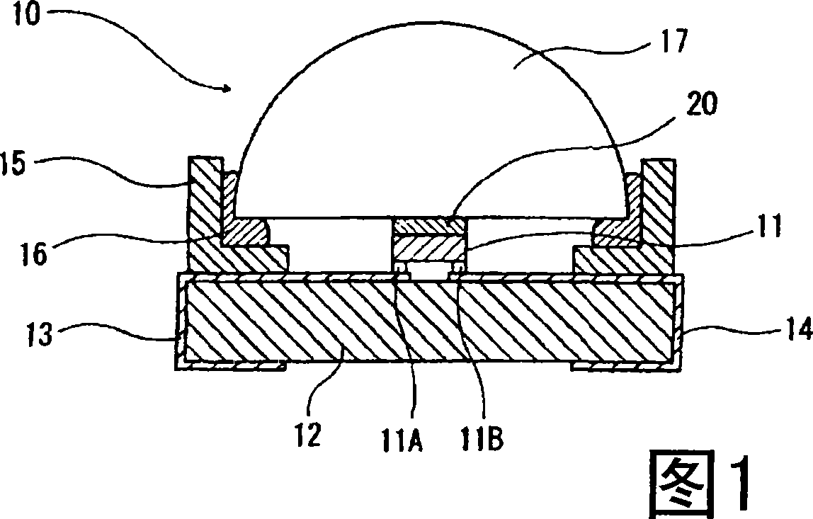
[0065] FIG. 1 is a schematic cross-sectional view showing the structure of one example of the ultraviolet light emitting device package of the present invention.

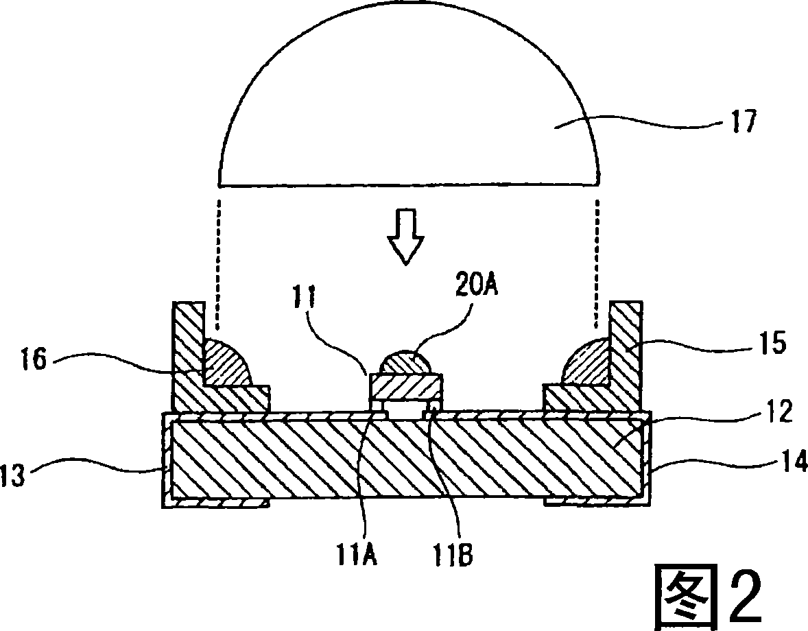
[0066] The ultraviolet light-emitting element package 10 emits ultraviolet light by being supplied with electric power. Light emitting direction front (upper in Fig. 1), the hemispherical condensing lens 17 that condenses the ultraviolet ray that emits from UV-LED element 11, separates the bottom surface and the light-emitting surface of UV-LED element 11 In the state of opening to form a gap of a predetermined size, it is held and fixed by the lens holding member 15 arranged around the periphery of the UV-LED element 11, whereby the UV-LED element 11 and the condenser lens 17 are integrally formed. .

[0067] The UV-LED element 11 is located at the center of the bottom surface side of the condensing lens 17 , and is electrically connected to the outside through lead electrodes 13 and 14 arranged on the substrate 1...


PUM


Abstract

The present invention provides an ultraviolet ray emitting element package that has a novel structure and is equipped with a condenser lens, for a high taking-out efficiency of ultraviolet ray and stable output. The ultraviolet ray emitting element package includes a condenser lens, and an ultraviolet ray emitting element positioned at the center on the bottom surface side thereof, away from the bottom surface of the lens. A refractive index difference buffering material having ultraviolet resistance is filled at least in the gap between the ultraviolet ray emitting element and the bottom surface of the condenser lens. A silicon resin or fluorine resin is used as the refractive index difference buffering material.

Description

Contents of the invention [0001] The present invention relates to an ultraviolet light emitting element package in which an ultraviolet light emitting element that emits ultraviolet rays and a condensing lens that condenses ultraviolet light from the ultraviolet light emitting element are integrated. Background technique [0002] Now, for example, an ultraviolet irradiation device that irradiates ultraviolet rays with a wavelength in the range of 300 to 400 nm centered on 365 nm is used to cure or dry adhesives, paints, inks, photoresists, etc. that have sensitivity in this wavelength range In various treatments such as processing, or conversely, melting or softening. [0003] For example, in light irradiation processing such as bonding of a pickup lens for an optical disc or bonding of an electronic component to a substrate, it is necessary to irradiate a small area with light, and the ultraviolet radiation used for such processing A certain device in the device has the fo...

Claims


Application Information

Patent Timeline
IPC IPC(8): H01L33/00H01L33/56H01L33/58
CPCH01L33/58H01L33/52H01L2224/73253
Inventor 仲田重范渡边胜也
Owner USHIO DENKI KK
Why Eureka
Try Eureka