DC-DC converters having improved current sensing and related methods

A DC-DC and converter technology, applied in the field of precise measurement of inductor current, can solve problems such as A1 instability and adverse effects on performance

Inactive Publication Date: 2007-11-28
INTERSIL INC
View PDF0 Cites 13 Cited by
  • Summary
  • Abstract
  • Description
  • Claims
  • Application Information

AI Technical Summary

Problems solved by technology

This noise coupling is known to adversely affect performance and has required very fine PCB layout to minimize pin I SENSE+ capacitive coupling on
Usually try to put the I SENSE+X Bypassing is not feasible as this would place a pole at the feedback of amplifier A1, which could make A1 unstable

Method used


Image

  • DC-DC converters having improved current sensing and related methods
  • DC-DC converters having improved current sensing and related methods
  • DC-DC converters having improved current sensing and related methods

Examples


Embodiment Construction

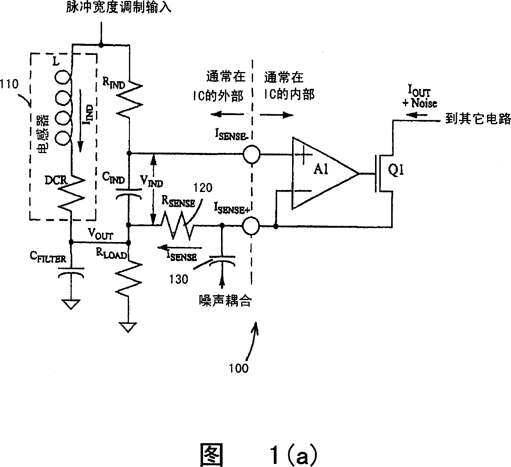
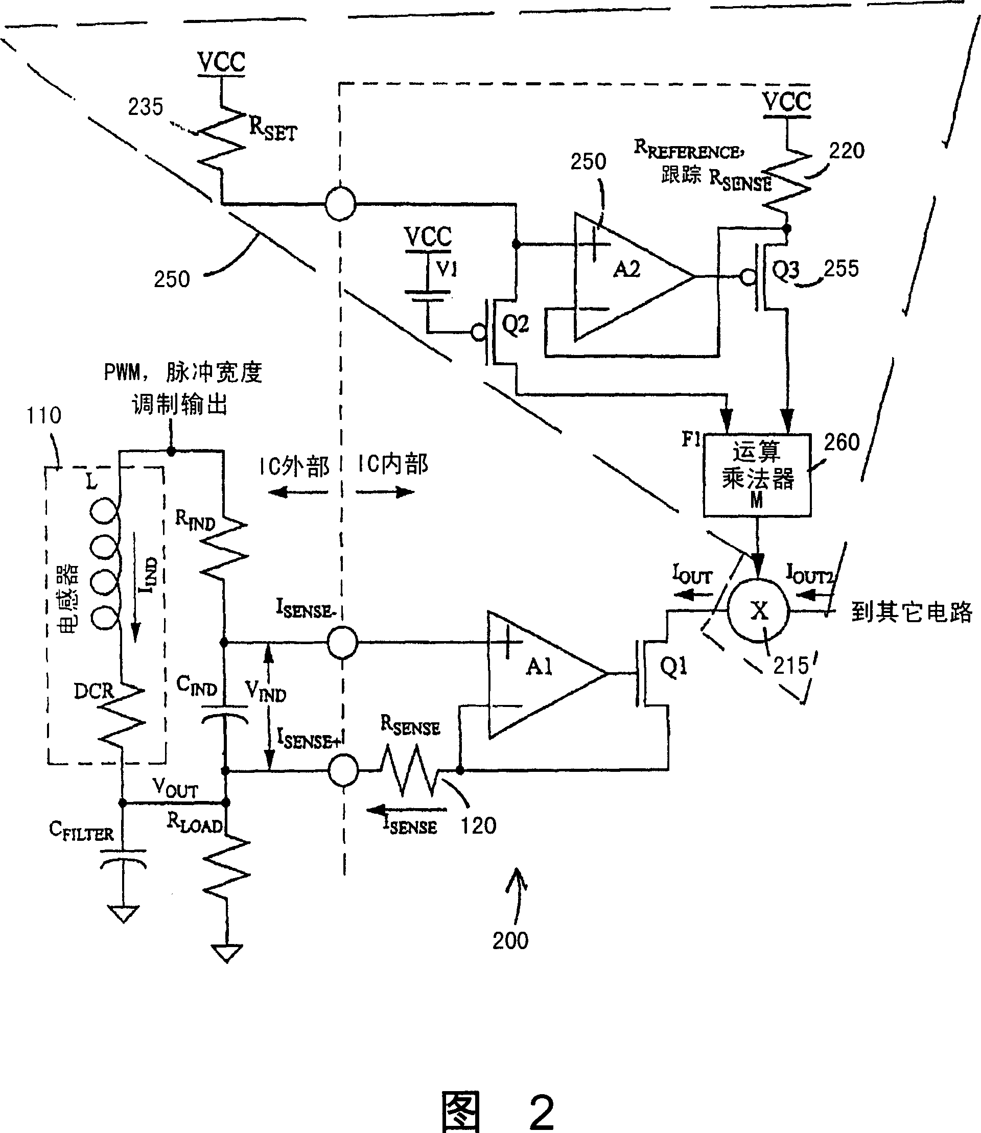
[0025] A circuit with an internal sense resistor for load current sensing in a DC-DC converter implementing inductor DCR sensing, or other switching regulation circuits, according to an embodiment of the present invention is shown in FIG. 2 . Circuit 200 includes the same circuit elements as in circuit 100 shown in FIG. The inductor current can be independent of R SENSE 120 actual value measurements. Like circuit 100, circuit 200 includes portions typically inside the IC and portions typically outside the IC (inductor L 110 and C FILTER usually external to the IC). However, unlike the circuit 100 shown in Figure 1, R SENSE inside the IC.

[0026] circuit 200 included in the I OUT path to the current multiplier 215 in order to form the I OUT Multiple, equal to M*I OUT The output current I OUT2 . The circuit 200 sets a second resistor R inside the IC REFERENCE 220. R REFERENCE 220 due to placing R on the chip SENSE Near 120, and by and R SENSE 120 are made of t...


PUM


Abstract

A DC-DC converter includes a chip including an error amplifier and a pulse width modulator (PWM) having an input connected to an output of the error amplifier, and an inductor driven by said PWM in series with an output node (VOUT) of the converter, wherein a load current flows through the inductor. VOUT is fed back through a network including a feedback resistor (RFB) to an inverting input of the error amplifier. A circuit for sensing the load current includes a first operational amplifier, a sense resistor on the chip having resistance RSENSE coupled to an inverting input of the first amplifier; wherein a sense current related to the load current flows through the sense resistor, a dependent current source provides an output current to supply the sense current. A reference resistor is disposed on the chip having a resistance RREFERENCE which is a fixed multiple of RSENSE. A set resistor is provided having a resistance RSET. Tracking circuitry sets a voltage across the reference resistor to be equal to a voltage across the set resistor. A function block is coupled to receive a current through the set resistor and a current through the reference resistor to find their ratio. A current multiplier is provided, wherein an output of the function block is coupled to the current multiplier. The current multiplier provides a measurement current which is proportional to the load current divided by RSET.

Description

[0001] RELATED APPLICATIONS This application claims priority to Provisional Application No. 60 / 808197, filed May 24, 2006, entitled "METHOD OFIMPROVED CURRENT SENSING IN DC-DC CONVERTERS," which is hereby incorporated by reference in its entirety. technical field [0002] The invention relates to accurate measurement of inductor current, especially for controlling switches in voltage regulation circuits and related power circuits. Background technique [0003] Accurate measurement of load current is required to facilitate control of various devices including current motors, DC-DC converter circuits, and voltage regulation circuits. A well-known circuit 100 for measuring load current through the inductor current flowing in a DC-DC converter is shown in Fig. 1(a). Pin I in circuit 100 SENSE- with I SENSE+ The portion to the right of the vertical dotted line between is usually inside the IC chip, while the part usually outside the IC chip includes the inductor L 110 and C FI...

Claims


Application Information

Patent Timeline
Patent Type & Authority Applications(China)
IPC IPC(8): H02M3/155H02M3/156
Inventor R・H・艾沙姆
Owner INTERSIL INC
Why Eureka
Try Eureka