
Heating device for an inhalation unit, inhalation unit and heating method

A technology of heating devices, equipment, applied in the direction of inhalers, heating elements, heating element shapes, etc.

Inactive Publication Date: 2007-12-05
VISHAY ELECTRONICS
View PDF1 Cites 21 Cited by
  • Summary
  • Abstract
  • Description
  • Claims
  • Application Information

AI Technical Summary

Problems solved by technology

[0004] Ending the heating process with a corresponding signal from the thermostat does not always ensure ideal heat transfer to the heat store and exact reaching of the target temperature

Method used


Image

  • Heating device for an inhalation unit, inhalation unit and heating method
  • Heating device for an inhalation unit, inhalation unit and heating method
  • Heating device for an inhalation unit, inhalation unit and heating method

Examples


Embodiment Construction

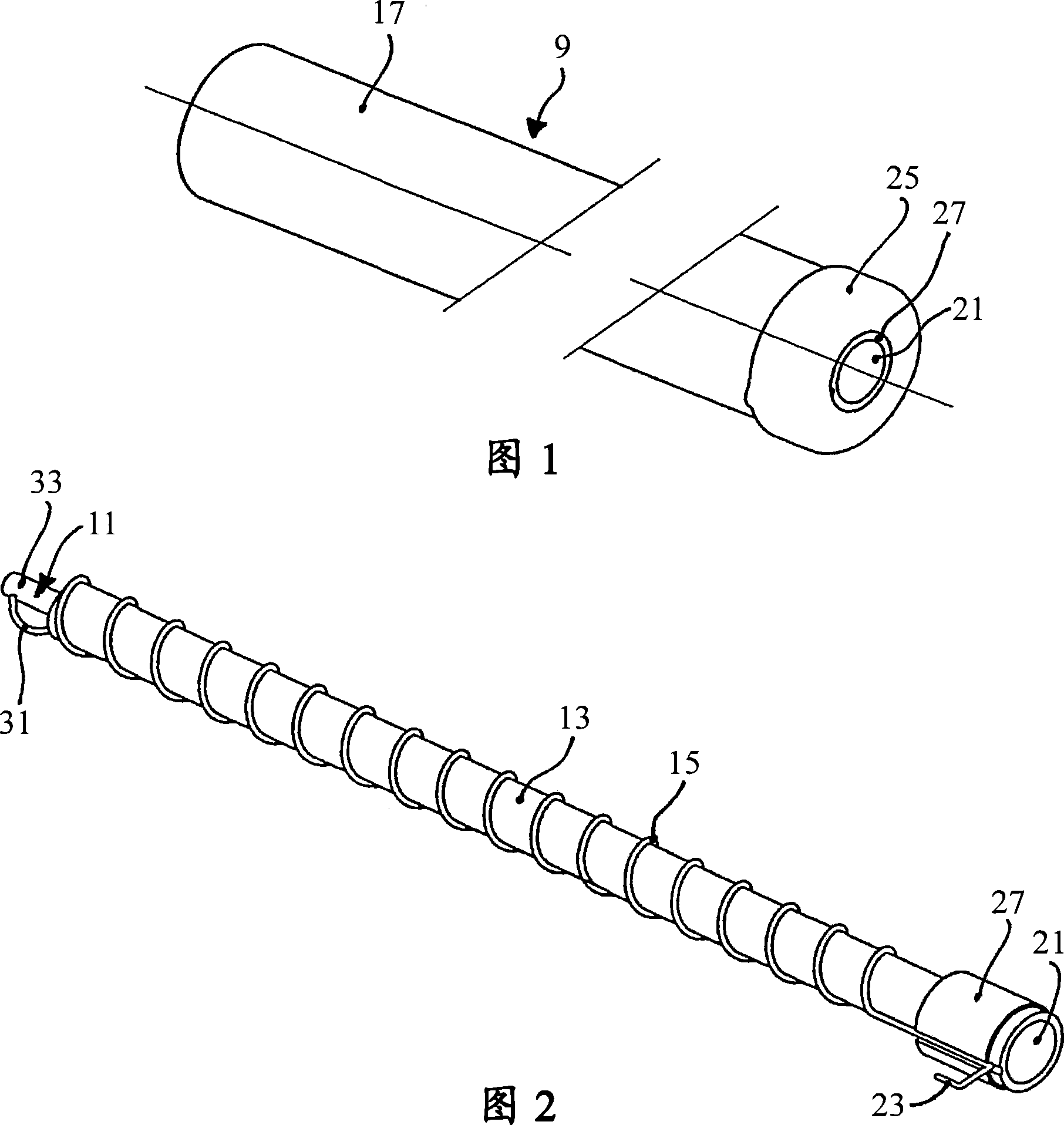
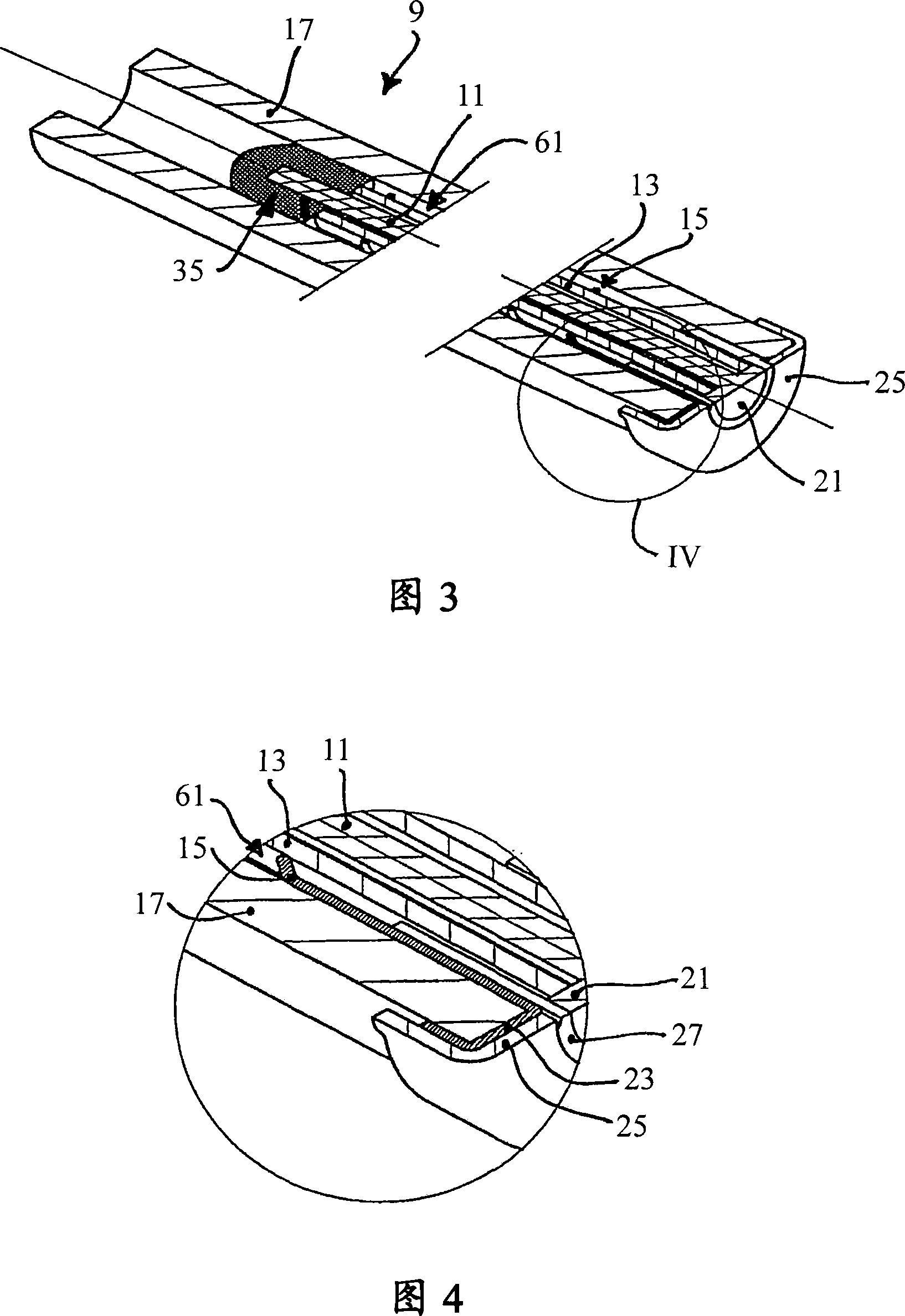
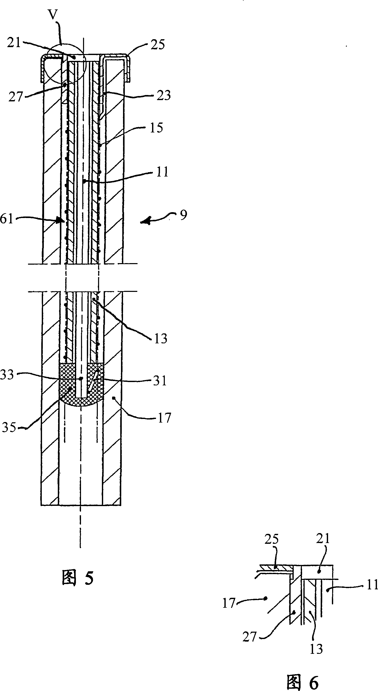
[0029] The heating device 9 shown in FIGS. 1 to 6 has an elongated shape with an almost rotationally symmetrical structure. The heating device 9 has (radially from the inside to the outside) a central contact pin 11 , a ceramic inner tube 13 , a heating coil 15 and a ceramic outer tube 17 (cf. FIGS. 3 and 5 in particular). The central contact pin 11 , the ceramic inner tube 13 , the heating coil 15 and the ceramic outer tube 17 are arranged coaxially with each other. The central contact stud 11 has a high electrical conductivity and consists, for example, of copper-nickel or another metal alloy.

[0030] The heating coil 15 has relatively high electrical resistance. This coil is used to heat the inner tube 13 and the outer tube 17 and has a high temperature coefficient, as described in detail next (FIG. 8). For example, a nickel-iron alloy "Resisthen" (registered trademark) consisting of various components: aluminum (0.6% by mass), chromium (0.3%), iron (30%), manganese (0.5...


PUM


Abstract

The invention relates to a heating device , for a mobile inhalation unit for the inhalation of active agents, comprising a heating wire (15), with two connector ends (23, 31) for the introduction of electrical energy and a thermal reservoir (13, 17) for heating air flowing along the thermal reservoir, whereby the thermal reservoir may be heated by means of the heating wire(15). The heating wire has a temperature coefficient of at least 0.001 K<-1>.The invention further relates to an inhalation unit with such a heating device and a method for heating a thermal reservoir on such a heating device.

Description

technical field [0001] The invention relates to a heating device for a mobile inhalation device for inhaling active substances, the heating device having a heating wire with two connections for supplying electrical energy and a heat store for heating air The air flows along the thermal storage, which can be heated by heating wires. Background technique [0002] Such inhalation devices are designed for the inhalation of active substances, in particular medicinal and / or aromatic substances. A user of such an inhalation device inhales air, which first flows along the heat store and is thereby heated. The heated air then flows along the active substance store, wherein the active substance present in the active substance store is released by the heated air, mixed into the heated air and finally inhaled by the user. [0003] A smokeless cigarette is known from WO 2004 / 098324 A2. This cigarette has a replaceable part (nicotine reservoir), also has a reusable part with sleeve and...

Claims


Application Information

Patent Timeline
IPC IPC(8): A61M15/06H05B3/42A24F47/00H05B3/06A61M11/04A24F40/20A24F40/46A24F40/485
CPCA61M11/041A61M2205/3368A61M2205/3646A61M2011/042H05B3/42A61M11/042H05B3/06A61M2205/3653A61M15/06A24F40/46A24F40/485A24F40/20
Inventor 恩斯特·赫布里希奥托·汉普尔诺贝特·彼佩尔
Owner VISHAY ELECTRONICS
Learn More