Multiphase mixing process using microchannel process technology

A technology of multiphase mixture and microchannel, which is applied in the direction of mixing methods, mixers, fluid mixers, etc., can solve the problem of low gas efficiency

A technology of multiphase mixture and microchannel, which is applied in the direction of mixing methods, mixers, fluid mixers, etc., can solve the problem of low gas efficiency

CN101084061AInactive Publication Date: 2007-12-05VELOCYS CORPORATION

Image

  • Multiphase mixing process using microchannel process technology
  • Multiphase mixing process using microchannel process technology
  • Multiphase mixing process using microchannel process technology

Examples


Embodiment 1

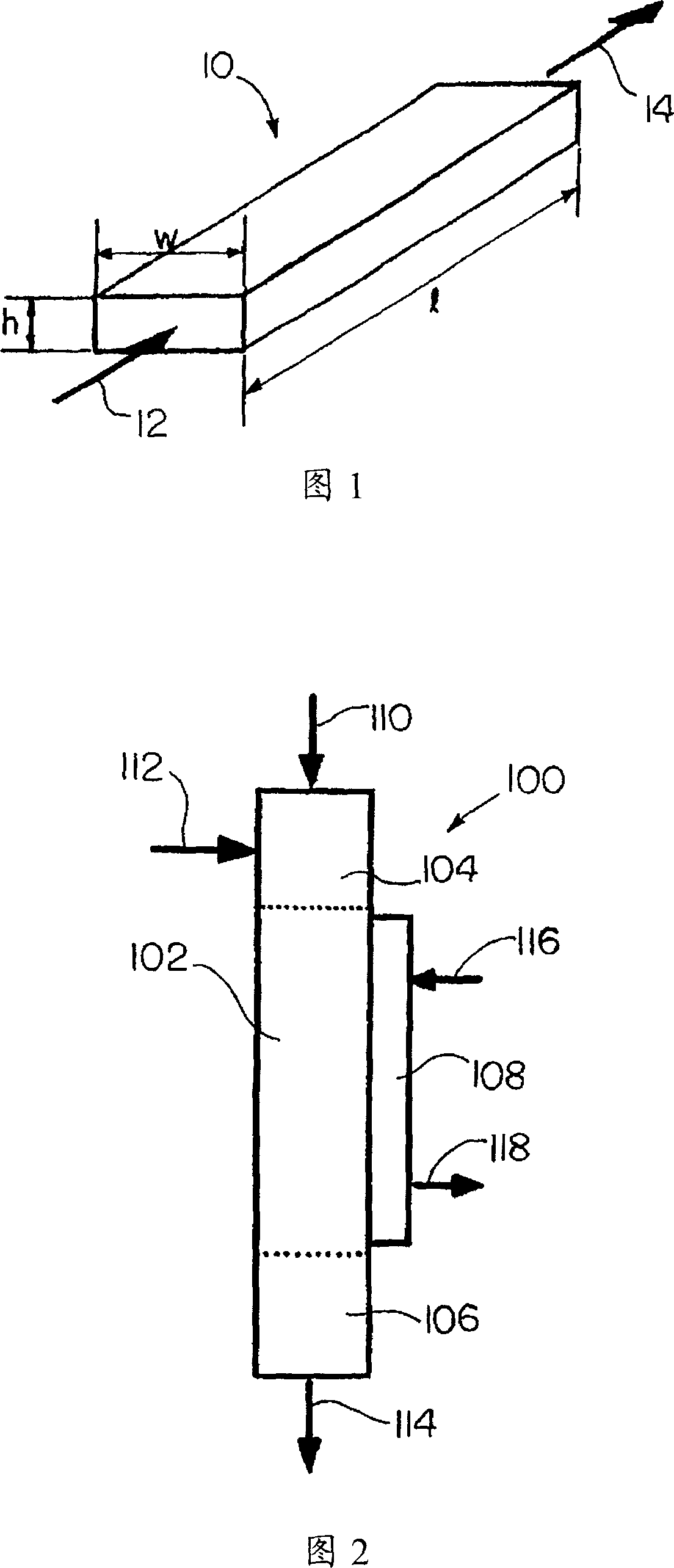
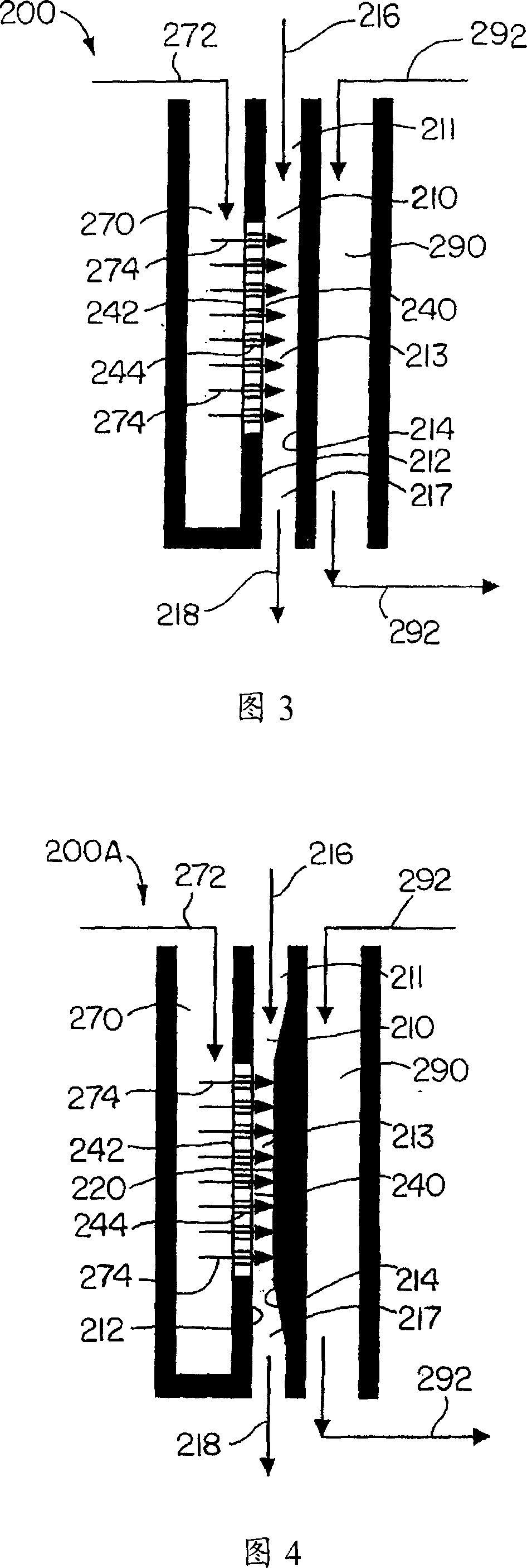
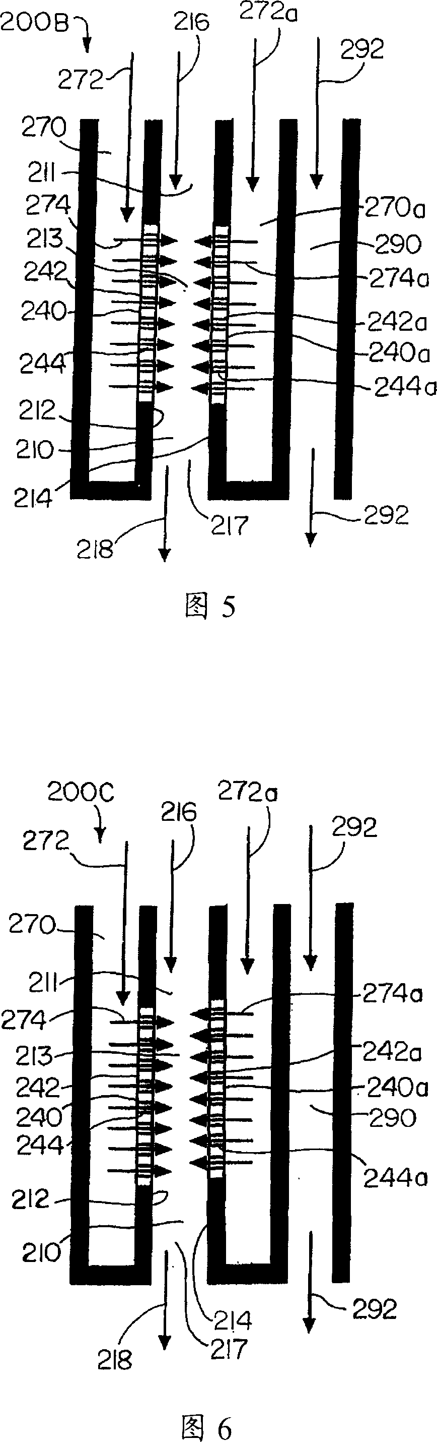
[0171] A multiphase mixer was fabricated comprising acrylic craft microchannels with rectangular cross-sections and internal dimensions of 0.040 x 1.25 x 3 inches (1.02 x 31.75 x 76.2 mm). There is an apertured region in one sidewall of the process microchannel. The apertured region had a nominal pore or pore size of 0.1 microns and an internal dimension of 0.010 x 1 x 1.5 inches (0.254 x 25.4 x 38.1 mm). The perforated area was constructed of stainless steel 316L and was supplied by Mott Company of Farmington, CT under catalog number 1110-12-12-018-01-A. The perforated area is connected with the gas supply box distribution gas and pipelines so that the gas flows through the perforated area and enters the process microchannel. The process microchannels are connected with tubing to allow liquid to flow through the process microchannels. The gas flows through the perforated region into the process microchannels to contact the liquid flowing through the process microchannels. ...

Embodiment 2

[0173] The method described in Example 1 was carried out using a gas flow rate of 2 SCCM and a liquid flow rate of 60 ml / min.

Embodiment 3

[0175] The method described in Example 1 was carried out using hydrogen as the gas and 1-hexene as the liquid.


PUM


Abstract

The disclosed invention relates to a process for making a multiphase mixture, comprising: flowing a first fluid stream through a process microchannel, the first fluid stream comprising at least one liquid and / or at least one gas, the process microchannel having an apertured section; flowing a second fluid stream through the apertured section into the process microchannel in contact with the first fluid stream to form the multiphase mixture, the second fluid stream comprising at least one gas and / or at least one microbody-forming material, the first fluid stream forming a continuous phase in the multiphase mixture, the second fluid stream forming a discontinuous phase dispersed in the continuous phase.

Description

technical field [0001] The invention relates to a multiphase mixing method using microchannel technology. Background technique [0002] Dispersion of air bubbles in a liquid can be used for chemically reactive or non-chemically reactive gas-liquid contact to facilitate absorption or desorption, or for foam or bubble generation. Examples of these include: air sparging to meet BOD (Biological Oxygen Demand) requirements of waste streams; air sparging for mixing liquids in containers; air sparging to stimulate microbial growth for hazardous waste treatment; nitrogen sparging for canning salads Dressing or Mustard, CO 2 Injection for carbonated beverages and beer; chlorine injection for bleaching pulp in paper manufacturing; air injection for coal flotation and other solids separation; nitrogen injection to remove residual water from motor oils; oxygen or air injection for fermentation Promotes cell growth during reactions; sparging air, oxygen, or other gases into reactors fo...

Claims


Application Information

Patent Timeline
05 Dec 2007
Publication
CN101084061A
IPC
B01J19/00; A61K8/06; A61Q19/00; B01F3/08; B01F5/04; B01F13/00; B01F15/06; F28D9/00; A23L27/18; A23L27/60; A23L29/00; B01F23/30; C09K23/00
CPC
B01J2219/00826; B01J2219/0086; B01J2219/00828; F28F3/12; F28D2021/0052; Y10S516/929; B01F3/0446; B01F15/065
Inventors
安娜·利·通科维奇; 劳拉·J·席尔瓦