
Liquid treatment device and method

A liquid, distillation device technology, applied in chemical instruments and methods, energy waste water treatment, water/sewage treatment, etc., can solve problems such as expensive, time-consuming operation, and production shutdown

Inactive Publication Date: 2007-12-05
AQUAMILL FIVE STAR
View PDF0 Cites 6 Cited by
  • Summary
  • Abstract
  • Description
  • Claims
  • Application Information

AI Technical Summary

Problems solved by technology

[0026] Large-scale fresh water installations need to add anti-corrosion measures, prepare and replace corroded elements, even replace heating elements and clean the entire system, so it is easy to have a relatively long shutdown
[0027] While the various distillation methods available are effective, they are still time consuming and expensive to operate

Method used


Image

  • Liquid treatment device and method

Examples


Embodiment Construction

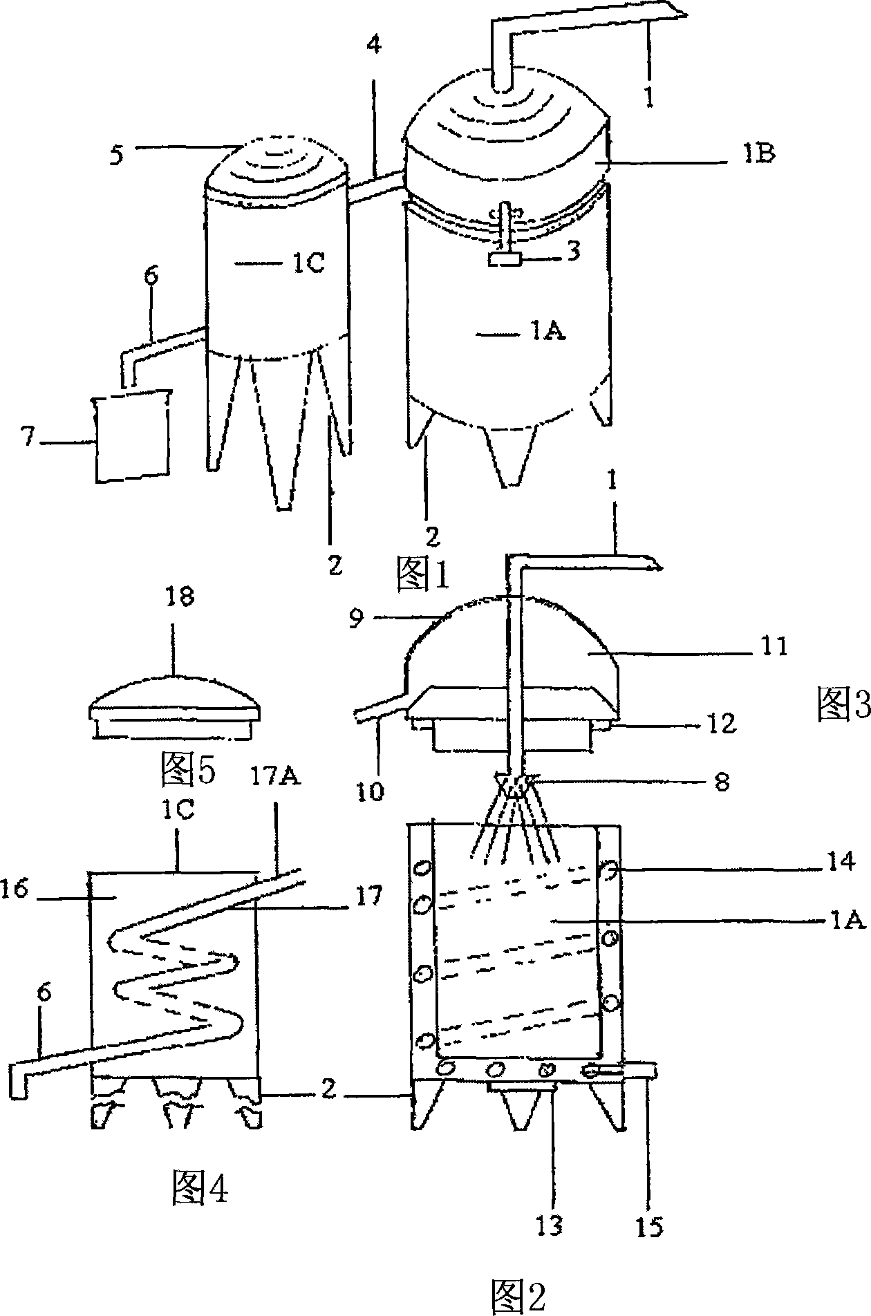
[0136] According to Fig. 1, this distillation device is made up of these two big components of a boiling cylinder 1A with a top cover 1B and a condenser 1C. The pressure water inlet pipe 1 is fixed on the top cover 1B and is used for providing the liquid that needs to be distilled. The second pipe 4 is responsible for conveying the condensed steam flowing out of the top part 1B to the condenser 1C. A pair of clamps 3 are respectively installed on the top cover 1B and the boiling cylinder 1A to fasten these two parts.

[0137] According to further illustrations in FIGS. 2 and 3 , the pipe 1 extends downward into the top cover 1B and passes through the top cover 1B to the boiling cylinder 1A. Although Fig. 2 and Fig. 3 show that the terminal of the pipeline 1 is relatively above the boiling cylinder 1A; but when the top cover 1B is placed on the boiling cylinder 1A, the terminal of the pipeline 1 will be near the center of the top of the boiling cylinder 1A. The design that th...


PUM


Abstract

A distillation device for treating liquid to be purified comprising: a) a boiler having an upper chamber (1B) and a lower chamber (1A); b) a liquid delivery system (1) for delivering the liquid to the lower chamber (1A); c) a heater (14) to heat the lower chamber (1A) to a predetermined temperature at which the liquid will be vaporized upon entering and / or contacting a surface of the lower chamber (1A); d) a vapor collector (9, 11) located in the upper chamber (1B) to receive and collect the vapor emanating from the lower chamber (1A); and e) a condenser (1C) in communication with the vapor collector (9, 11) to receive and condense that vapor into purified liquid.

Description

technical field [0001] The invention relates to a liquid treatment device and treatment method, which can be used for all liquids requiring distillation treatment. This technology can also reduce the energy consumption of hot water heating devices, such as water heater tanks. [0002] Another object of this invention is to provide an innovative and effective method of purification of sewage or sea water, this unique distillation method is faster than the existing conventional methods. The technology also produces a useful by-product, sodium chloride, while desalinating seawater; the invention is also environmentally friendly because no toxic waste residues are to be dealt with. [0003] This technology not only includes the method of moving sodium chloride from the boiling chamber of the still to the storage tank, but also provides a means for automatic cleaning of the distillation unit. [0004] Slight modifications to this technology can be used with hot water heating devi...

Claims


Application Information

Patent Timeline
IPC IPC(8): C02F1/12
CPCY02A20/124Y02W10/37
Inventor F·W·米勒
Owner AQUAMILL FIVE STAR
Learn More