
Optical fiber displacement sensor

A displacement sensor, fiber laser technology, applied in the direction of using optical devices to transmit sensing components, instruments, using optical devices, etc., can solve the problems of reducing the signal-to-noise ratio, high requirements for grating matching, and small measurement range, and achieves signal-to-noise ratio. The effect of high ratio, high detection accuracy and strong optical signal

Inactive Publication Date: 2007-12-26
SHANGHAI INST OF OPTICS & FINE MECHANICS CHINESE ACAD OF SCI
View PDF0 Cites 4 Cited by
  • Summary
  • Abstract
  • Description
  • Claims
  • Application Information

AI Technical Summary

Problems solved by technology

However, this method requires high grating matching, the measurement range is not large, and the response speed is low. It is not suitable for high-frequency measurement, and the measurement accuracy is affected by the nonlinearity of PZT.
[0008] Broadband light source / interference receiving method: the biggest advantage is that the resolution is 846.3pm~2780.7pm, but the disadvantage is that it is not suitable for static detection
[0009] Tunable narrow-band light source / broadband receiver method, it is reported that the highest resolution of this method can reach 23pm, but the pump light source needs high power and is easy to excite multi-mode, which reduces the signal-to-noise ratio and is inconvenient for multiplexing

Method used


Image

  • Optical fiber displacement sensor
  • Optical fiber displacement sensor
  • Optical fiber displacement sensor

Examples


Embodiment Construction

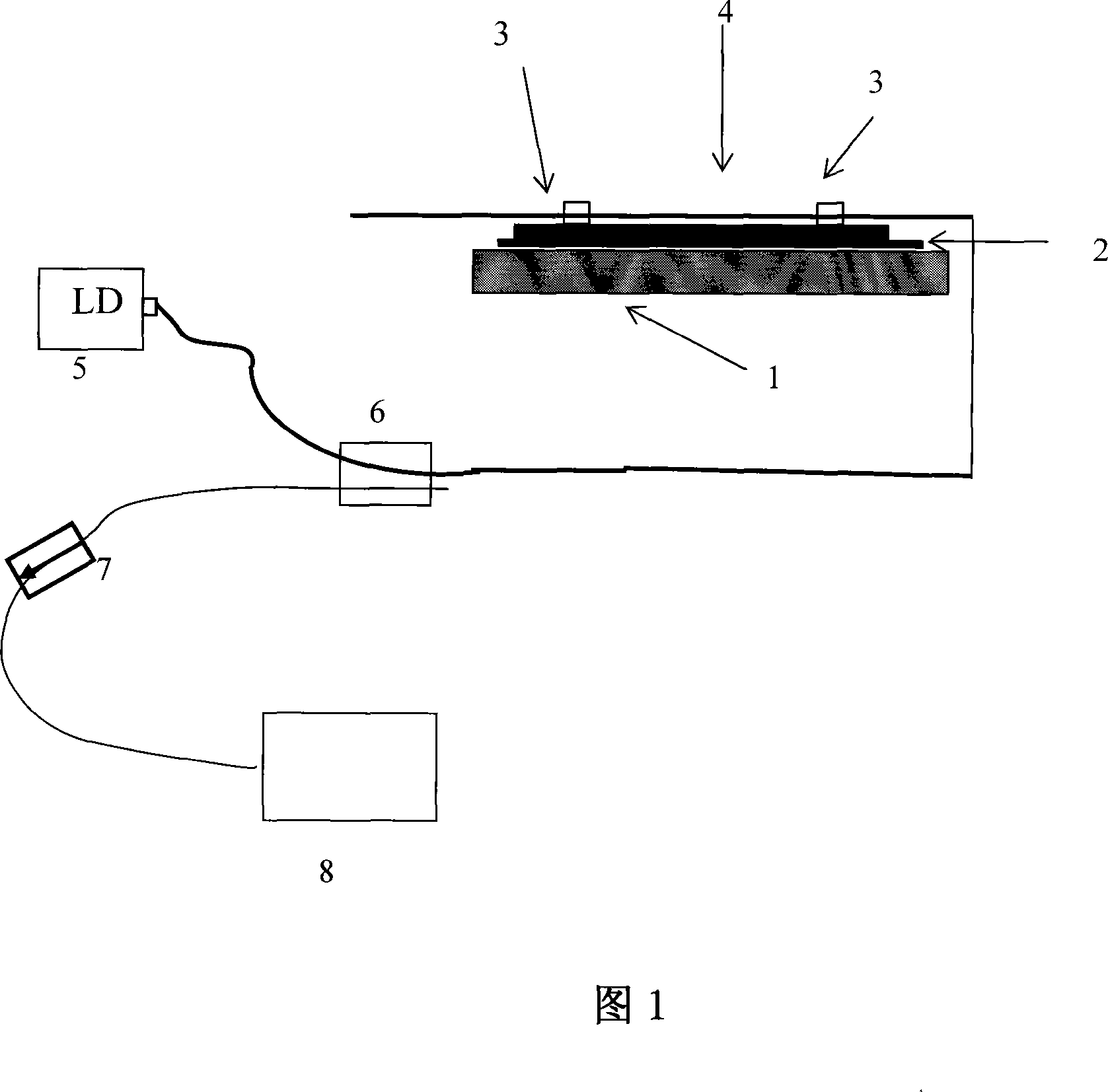
[0020] Please refer to Fig. 1 earlier, Fig. 1 is the schematic block diagram of the structure of the optical fiber displacement sensor of the present invention, as seen from the figure, the optical fiber displacement sensor of the present invention, it is constituted as: a semiconductor laser 5 links to each other with the wavelength division multiplexer 6 through the optical fiber, the wave length The straight-through end of the division multiplexer 6 is connected with the DFB fiber laser 4 of 1053nm, and the output end of the wavelength division multiplexer 6 is connected with the fixed F-P spectrum analysis device 8 through the fiber isolator 7, and the DFB fiber laser 4 is connected with an ultraviolet The silica gel 3 is encapsulated on the aluminum strip 2 .

[0021] During use, we fix the two ends of a 10cm long Yb-doped fiber DFB fiber laser 4 on an object 1 that needs to detect its length change with ultraviolet silica gel 3 . When the length of the object changes, th...


PUM


Abstract

A displacement transducer of optical fiber is prepared for connecting semiconductor laser to wavelength division multiplexer through optical fiber, connecting direct-through end of said multiplexer to DFB optical laser and connecting output end of said multiplexer to fixed F-P spectrum analysis unit through optical fiber isolator.

Description

technical field [0001] The invention relates to an optical fiber sensor, which is an optical fiber sensor for detecting micro-displacement changes, and can be used for detecting cracks in bridges, buildings and dams and micro-displacement changes in scientific experiments. Background technique [0002] By writing a grating on the Yb-doped fiber, a Yb-doped distributed feedback (hereinafter referred to as DFB) fiber laser is obtained. Generated at the geometric center of a uniformly written DFB fiber laser phase shift, a single longitudinal mode fiber laser is produced. The wavelength of such lasers is determined by: [0003] λ=2nΛ [0004] Among them, λ is the operating wavelength of the DFB laser, n is the effective refractive index of the fiber, and Λ is the grating period. When the value of the grating period Λ is changed, the operating wavelength of the DFB fiber laser is also changed. [0005] At present, in the detection of strain, crack and displacement in bridg...

Claims


Application Information

Patent Timeline
Patent Type & Authority Applications(China)
IPC IPC(8): G01B11/02G01D5/353
Inventor 陈嘉琳王利李国扬常丽萍韩悦
Owner SHANGHAI INST OF OPTICS & FINE MECHANICS CHINESE ACAD OF SCI
Learn More