Touching screen

A touch screen and lead-out electrode technology, applied in printed circuit, instrument, electrical digital data processing, etc., can solve the problems of time-consuming inspection, time-consuming and labor-intensive, difficult judgment, etc., and achieve easy production, reliable electrical contact and contact separation Effect

Inactive Publication Date: 2008-01-02
PANASONIC CORP
View PDF1 Cites 2 Cited by
  • Summary
  • Abstract
  • Description
  • Claims
  • Application Information

AI Technical Summary

Problems solved by technology

[0019] However, in the above-mentioned conventional touch panel, when bonding and connecting the wiring board 8, it takes time and labor to confirm the heating temperature and the bonding state, and when the resistance value or the bonding state deviates, the judgment is changed. It is difficult to obtain, so there is a problem that it takes time to check

Method used


Image

  • Touching screen
  • Touching screen
  • Touching screen

Examples


Embodiment approach

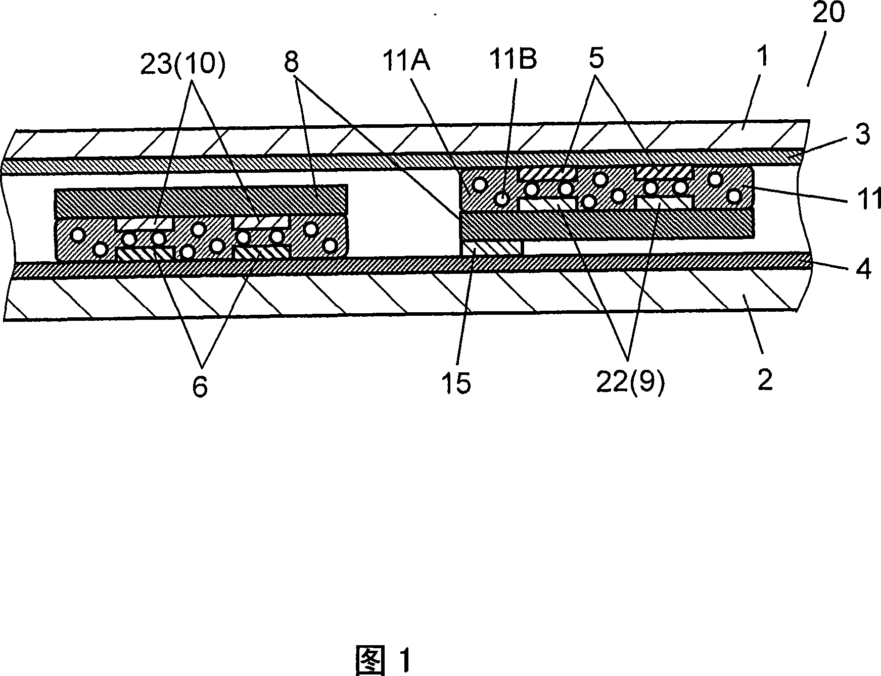
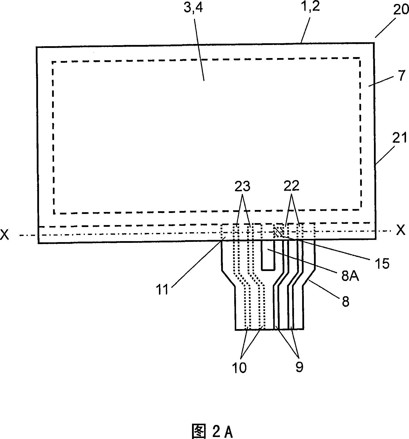
[0030] 1 and 2A are diagrams illustrating a touch panel according to an embodiment of the present invention. Among them, FIG. 1 shows a cross-sectional view taken along line X-X in FIG. 2A.

[0031] The touch panel 20 of this embodiment has a panel portion 21 and a wiring board 8 . The panel unit 21 has a light-transmitting upper substrate 1 in the form of a film such as polyethylene terephthalate or polycarbonate, and a light-transmitting lower substrate 2 such as glass, acrylic resin, or polycarbonate. A translucent upper conductive layer 3 such as indium tin oxide or tin oxide is formed on the lower surface of the upper substrate 1 , and a lower conductive layer 4 made of the same material is formed on the upper surface of the lower substrate 2 . As a method for producing the upper and lower conductive layers 3 and 4, for example, a thin film forming method such as sputtering or vacuum deposition can be used.

[0032] On the upper surface of the lower conductive layer 4, ...


PUM

PropertyMeasurementUnit
melting pointaaaaaaaaaa

Abstract

The present invention relates to a touch screen with thermal-sensitive color-changing portion near the connecting situation adhered by heating. According to colored state of the thermal-sensitive color-changing portion, can easily affirm whether processing to heat and press with set temperature when connecting distributing substrate, therefore can obtain a making easily and electric contacting-separating reliable touch screen.

Description

technical field [0001] The present invention relates to a touch screen mainly used in the operation of various electronic devices. Background technique [0002] In recent years, various electronic devices, such as mobile phones and car navigation systems, have become more functional and diversified. Accordingly, devices in which a light-transmissive touch panel is mounted on the front of a display element are increasing. Devices capable of switching various functions by pressing the touch panel with a finger, a pen, etc. while checking the display of the display element on the rear surface through the touch panel are increasing. Therefore, a touch panel with excellent visibility and reliable operation is required. [0003] A conventional touch panel will be described using FIG. 4 and FIG. 5 . Wherein, in order to make the structure easy to understand, the dimensions in the thickness direction are enlarged and displayed in the drawings. FIG. 4 is a sectional view of main ...

Claims


Application Information

Patent Timeline
Patent Type & Authority Applications(China)
IPC IPC(8): G02F1/133G06K11/06
CPCH05K2201/052H05K1/147H05K1/144G06F3/041H05K3/361H05K3/323G06F3/04164G06F3/045
Inventor 田边功二藤井彰二
Owner PANASONIC CORP
Why Eureka
Try Eureka